Categories: Featured Articles » Novice electricians
Number of views: 57937
Comments on the article: 4
Boolean algebra. Part 3. Contact schemes
 The article describes the basic principles of designing relay circuits in accordance with a given algorithm of their operation.
In two previous articles was told about the basics Boolean algebra and relay algebra. On this basis, structural formulas were developed, and already typical contact circuits were developed on them.
Drawing up a structural formula according to a ready-made scheme is a simple matter. It is much more difficult to present the electrical circuit of the future machine according to the ready-made structural formula. It needs some training!
Figure 1 shows the most common options. contact circuits and their equivalents. They will help in the preparation of electrical circuits of machines, as well as analyze ready-made structures, for example, in the process of repairing them.
How can you use the options for contact circuits discussed above?
Consider the circuit shown in Figure 2, a. The corresponding structural formula has the form: (A + B) * (C + D).
Using the distribution law of Boolean algebra, we open the brackets in this expression and get: A * (C + D) + B * (C + D), which corresponds to the scheme shown in Figure 2, b. Further, due to multiplication, we can obtain the formula A * C + A * D + B * C + B * D, corresponding to Figure 2, c.
All three schemes are equivalent, that is, they turn out to be closed under the same conditions. However, they are different in complexity.

Figure 1. Typical contact circuits
The first of the circuits, the simplest, it requires four relays, each of which must have one normally open contact. (To simplify the drawings, relay coils are not shown).
Scheme "b" requires a relay with two contact groups. Actually, the main task of the algebra of contact circuits is to find all equivalent circuits so that you can choose the simplest one from them.

Figure 2. Equivalent contact circuits.
To consolidate the material covered, try to solve the following problems yourself.
1. Draw the circuit diagram of an automaton having the structural formula A * B * C * D + A * B * E + A * D.
2. Prove that the circuits shown in Figure 3, a and b, are equivalent.
3. Simplify the circuit shown in Figure 3, c.
4. What structural formula implements the scheme in Figure 3, d?

After what we have already studied, it will be possible to start solving the tasks that were set at the very beginning of the first article. We recall them briefly.
The first task was to turn on and off the light bulb in the room with three switches located in different places: at the door, at the table, at the bed.
The second task is to vote sports judges: out of four judges “FOR” must vote at least two, provided that “FOR” the chairman of the commission voted.
The third task was just for educational purposes. It proposed the same as in the first, only for six switches, as if there were six walls in the room. Similar circuits are just being developed using the algebra of relay circuits.
In general, if we want to develop a scheme that has some specified logical properties, then we can approach this problem in two different ways. Conventionally, these paths can be called “intuitive” and “algebraic”.
Some tasks are better solved in the first way, while others in the second. The intuitive approach turns out to be more convenient when the operation of the circuit is controlled by many switches, but there is some symmetry in the mutual arrangement of these relays. We will see that here an intuitive approach leads to the goal faster, while using the relay algebra apparatus in the case of many variables can be very cumbersome. It is useful to get acquainted with both possible approaches to solving this problem.
Let's start with an intuitive approach. Suppose we needed to build a circuit that was closed when all n control relay circuits worked.
The solution to this problem does not require long deliberation: it is clear that the set condition will be fulfilled if interconnected sequentially n normally open relay contacts.
Similarly, it is obvious that to build a circuit that closes when at least one of the n relays has tripped, it is enough to connect n normally open relay contacts in parallel.
It is easy to imagine a circuit that closes when some, but not all, relays are triggered. Such a circuit is shown in Figure 4, a. On the right is a diagram that operates on the principle of "all or nothing." It will be closed only when all relays are activated or the relays are disconnected (Figure 4, 6).
Consider now a more complex example. Let there be n contacts located in a certain specific sequence: A, B, C, D, E, F ... We will construct a circuit that closes when any k series-connected contacts are closed, and only they are. Such a scheme for the values n = 7 and k = 3 is shown in Figure 4, c. The method for constructing such schemes for any other values of n and k is clear from this figure.

We proceed to the construction of circuits according to the given conditions of their work using relay algebra.
As before, the operating conditions of the circuit are always always first set verbally. The designer, first of all, must be able to put into words what he wants. If he does not have such clarity, then no algebra will help. You should always start with a clear statement of the requirements that are set before the new scheme. As in any business, this task is perhaps the most difficult. If the conditions are simple enough, then we can immediately write an expression of a structural formula that satisfies these requirements.
Example 1 Suppose we have to build a circuit containing 4 contacts A, B, C and D so that the circuit is turned on when contact A is closed, and one of the other three contacts. In this simple case, the operation of the circuit in verbal writing will look like this: “The circuit should conduct current if contacts A and B are closed, or contacts A and C or contacts A and D. Agree that now it is very simple to draw up a structural formula. It will look like this:
A * B + A * C + A * D = 1 or A * (B + C + D) = 1.
The circuit has two options. They are shown in Figure 5. The second option does not require a relay with three normally open contacts.

Example 2 The first article was task number 2 on the voting of sports judges. Read its condition more closely, it is similar to the example just examined. A clearer verbal record of the requirements will look like this: “It is necessary to draw up a circuit containing 5 contacts A, B, C, D, E, so that it conducts current and turns on the display lamp if the following contacts are closed:
A and B and C, or A and B and D, or A and B and E, or A and C and D, or A and C and E, or A and D and E. Contact A is the chairman button. If it is not pressed, then each of the 6 logical products will be 0, i.e. Voting did not take place.
The structural formula will be as follows:
(A * B * C) + (A * B * D) + (A * B * E) + (A * C * D) + (A * C * E) + (A * D * E) = 1,
or A * (B * C + B * D + B * E + C * D + C * E + D * E) = 1.
Both variants of the circuit are shown in Figure 5, c and d. This is the solution to the problem.
Having some skill in reading structural formulas, it is easy to imagine the circuit of the automaton itself and all its capabilities. Interestingly, the algebra of relay circuits provides more information than even the circuit itself. It allows you to see how many and which relays are required. With its help, you can easily find the simplest version of the circuit machine.
Example 3 Having gained some experience in the preparation of structural formulas, we will try to solve the problem that started first article: you need to design a switch that allows you to turn on the light when entering the entrance and turn it off after you have climbed to the desired floor, or, conversely, turn it on when leaving the apartment and turn it off after you go down. The same situation happens in a long corridor: at one end, the bulb must be lit, and after going to the other end, extinguished. In short, the task boils down to controlling one light bulb from different places with two switches.
We choose the following procedure for solving the problem: first, we clearly formulate the operating conditions of the switches, then we write them in the form of a formula, and we will draw an electric circuit based on them.
So, that the bulb burned (1), it is necessary that one of two conditions was fulfilled:
1. Turn on the switch at the bottom (A) and turn off at the top (/ B). Enter the porch.
2. Turn on the switch at the top (B) and turn off the bottom (/ A). Leave the apartment.
Using the accepted notation, the structural formula is written as follows:
A * (/ B) + (/ A) * B = 1
The circuit diagram of the switch is shown in Figure 6. Currently, such switches are commercially available, these are feedthrough switches. Therefore, the consideration of these schemes here is given simply for the concept of the general principles of their work.
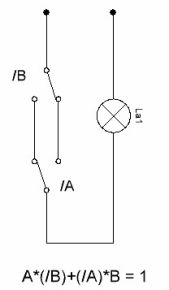
Figure 6
In task No. 1 at the beginning of the first article, we were talking about a scheme that allows you to turn on and off the light in the room with any of the three switches. Reasoning in the same way as in the case of two switches, we obtain the structural formula:
A * B * (/ C) + A * (/ B) + (/ A) * B * C = 1.
The scheme drawn up by this formula is shown in Figure 7.

Figure 7
At the beginning of the first article, a simple educational task No. 2 was proposed: as if there were six walls in the room, and each one had a switch. The logic of the circuit is exactly the same as for the three switches. Let us denote them by the letters A, B, C, D, E, F. Recall that the notation (/ A), (/ B) and so on, this is not a division sign, but a logical negation. More often indicated by underlining characters and, even whole expressions, on top. In some schemes, this underscore is simply replaced by a minus sign. So, the structural formula for the six switches is:
(/ A) * B * C * D * E * F + A * (/ B) * C * D * E * F + A * B * (/ C) * D * E * F + A * B * C *
(/ D) * E * F + A * B * C * D * (/ E) * F + A * B * C * D * E * (/ F) = 1.
Readers are invited to draw up a complete electrical circuit that implements this structural formula to acquire practical skills in designing circuits. A little hint: for the circuit you will need six relays, each of which has one normally open contact and five normally closed. Such complex relays, if necessary, can be assembled from several simpler ones by connecting their coils in parallel.
This concludes the story of Boolean algebra and the algebra of relay circuits.
Continuation of the article: Logic chips
Boris Aladyshkin
See also at bgv.electricianexp.com
: