Categories: Featured Articles » Practical Electronics
Number of views: 63932
Comments on the article: 6
Electronic passage switch
 The corridor switch is very familiar to older electricians. Now such a device is somewhat forgotten, so you have to briefly talk about the algorithm of its action.
Imagine that you leave a room in a corridor in which there are no windows. Click the switch near the door, and the light in the corridor lights up. This switch is conventionally called the first.
Having reached the opposite end of the corridor, before exiting to the street, you turn off the lights by the second switch located near the exit door. If someone else remains in the room, then he can also turn on the light with the first switch when exiting, and turn off with the help of the second. When entering the corridor from the street, the light is turned on by the second switch, and already in the room it is turned off by the first.
Although the whole device is called a switch, its manufacture will require two changeover switches. Conventional switches will not work here. A diagram of such a corridor switch is shown in Figure 1.

Figure 1. Corridor switch with two switches.
As can be seen from the figure, the circuit is quite simple. The lamp will light if both switches S1 and S2 are closed to the same wire, either the top or bottom, as shown in the diagram. Otherwise, the lamp is off.
To control one light source from three places, not necessarily one light bulb, it can be several lamps under the ceiling, the scheme is already different. It is shown in Figure 2.
Figure 2. Corridor switch with three switches.
Compared to the first scheme, this scheme is somewhat more complicated. A new element appeared in it - switch S3, which contains two groups of switching contacts. In the position of the contacts indicated in the diagram, the lamp is turned on, although the position at which the consumer is turned off is usually indicated. But with such an outline, it is easier to trace the current path through the switches. If now any of them are transferred to the position opposite to that indicated on the diagram, the lamp will turn off.
To trace the current path with other options for the position of the switches, it is enough just to move the finger according to the scheme and mentally transfer them to all possible positions.
Typically, this method allows you to deal with more complex schemes. Therefore, a long and boring description of the operation of the circuit is not given here.
This scheme allows you to control lighting from three places. It can be used in the corridor, which has two doors. Of course, one can argue that in this case it is easier to install a modern motion sensor, which even monitors whether it is day or night. Therefore, during the day the lighting will not turn on. But in some cases, such automation will simply not help.
Imagine that such a triple switch is installed in the room. One key is located at the front door, another above the desk, and a third near the bed. After all, automation can turn on the light when you just roll over from side to side in a dream. You can find many more conditions where a circuit without automation is needed. Such switches are also called walk-through, and not just corridors.
Theoretically such passage switch can be done with a large number of switches, but this will greatly complicate the circuit, all switches with a large number of contact groups will be required. Already even just five switches will make the circuit inconvenient for installation and just understanding the principles of its operation.
And if such a switch is needed for the corridor into which ten, or even twenty, rooms go? The situation is quite real. Such corridors are enough in provincial hotels, student and factory dormitories. What to do in this case?
This is where electronics come to the rescue. After all how does such a through switch work? They pressed one key - the light turned on and remains on until it pressed another. Such an operation algorithm resembles the operation of an electronic device - a trigger. You can read more about the various triggers in the series of articles “Logic chips. Part 8».
If you just stand and press the same key, the light will alternately turn on and off. This mode is similar to the operation of the trigger in the counting mode - with the advent of each control pulse, the state of the trigger changes to the opposite.
In this case, first of all, you should pay attention to the fact that when using a trigger, the keys should not have a fixation: just enough buttons, like bell keys. To connect such a button, you will need only two wires, and not very thick ones.
And if you connect another button in parallel with one button, you get a pass-through switch with two buttons. Without changing anything in the circuit diagram, you can connect five, ten or more buttons. The circuit using the K561TM2 trigger is shown in Figure 3.
Figure 3. Feed-through switch on the K561TM2 trigger.
The trigger is enabled in counting mode. To do this, its inverse output is connected to input D. This is a standard inclusion in which each input pulse at input C changes the trigger state to the opposite.
Input pulses are obtained by pressing the buttons S1 ... Sn. The R2C2 chain is designed to suppress contact bounce, and the formation of a single pulse. When the button is pressed, the capacitor C2 is charged. When you release the button, the capacitor discharges through the C - input of the trigger, forming an input pulse. This ensures clear operation of the entire switch as a whole.
The R1C1 chain connected to trigger input R provides a reset at initial power-up. If this reset is not required, then the R - input should simply be connected to a common power cable. If you leave it simply “in the air”, the trigger will perceive this as a high level and will always be in the zero state. Since the RS - inputs of the trigger are priority, the supply of pulses to the input C of the trigger state will not be able to change, the whole circuit will be inhibited, inoperative.
An output stage controlling the load is connected to the direct output of the trigger. The simplest and most reliable option is a relay and a transistor, as shown in the diagram. In parallel to the relay coil, a diode D1 is connected, the purpose of which is to protect the output transistor from the self-induction voltage when relay Rel1 is turned off.
The K561TM2 chip in one housing contains two triggers, one of which is not used. Therefore, the input contacts of an idle trigger should be connected to a common wire. These are contacts 8, 9, 10 and 11. Such a connection will prevent the microcircuit from malfunctioning under the influence of static electricity. For microcircuits of the CMOS structure, such a connection is always necessary. The supply voltage + 12V should be applied to the 14th output of the microcircuit, and the 7th output should be connected to a common power wire.
As a transistor VT1, you can apply KT815G, diode D1 type 1N4007. The relay is small-sized with a 12V coil. The working current of the contacts is selected depending on the power of the lamp, although there may be any other load. It is best to use imported relays like TIANBO or the like.
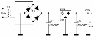
The power source is shown in Figure 4.
Figure 4. Power supply.
The power source is made according to a transformer circuit using an integrated stabilizer 7812, providing a constant voltage of 12V output. As a network transformer, a transformer with a capacity of not more than 5 ... 10 W with a secondary voltage of 14 ... 17V is used. The Br1 diode bridge can be used as type KTs407, or assembled from 1N4007 diodes, which are currently very common.
Imported electrolytic capacitors such as JAMICON or the like. They are now also easier to buy than domestic parts.Although the 7812 stabilizer has built-in protection against short circuits, it is nevertheless necessary to verify that the installation is correct before turning on the device. This rule should never be forgotten.
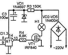
The power supply, made according to the specified scheme, provides galvanic isolation from the lighting network, which allows the use of this device in damp rooms, such as cellars and cellars. If there is no such requirement, then the power supply can be assembled using a transformerless circuit, similar to that shown in Figure 5.
Figure 5. Transformerless power supply.
This scheme allows you to abandon the use of a transformer, which in some cases is quite convenient and practical. True buttons, and the whole design as a whole, will have a galvanic connection with the lighting network. This should not be forgotten, and follow safety instructions.
The rectified mains voltage through the ballast resistor R3 is supplied to the Zener diode VD1 and is limited to 12V. Voltage ripple is smoothed by electrolytic capacitor C1. The load is turned on by the transistor VT1. In this case, the resistor R4 is connected to the direct output of the trigger (pin 1), as shown in Figure 3.
The circuit assembled from serviceable parts does not require adjustment, it starts working immediately.
Boris Aladyshkin
See also at bgv.electricianexp.com
:


