Categories: Featured Articles » Novice electricians
Number of views: 66615
Comments on the article: 0
Electricity metering devices - types and types, main characteristics
 Electric energy is transmitted over vast distances between different states, and is distributed and consumed in the most unexpected places and volumes. All these processes require automatic recording of passing capacities and the work they perform. The state of the energy system is constantly changing. It is necessary to analyze and competently manage the main technical parameters.
The measurement of the current power is assigned to wattmeters, the unit of measurement of which is 1 watt, and the work performed over a certain period of time is assigned to meters that take into account the number of watts per hour.
Depending on the amount of energy taken into account, the devices operate within kilo-, mega-, gigo- or tera-units. This allows:
-
by one main meter located at the substation providing power to a large modern city, to evaluate the terabytes of kilowatt hours spent on the consumption of all apartments and manufacturing enterprises of the administrative industrial and residential center;
-
a large number of devices installed inside each apartment or production, take into account their individual consumption.
Wattmeters and counters work due to the information on the state of the current and voltage vectors in the power circuit that is constantly supplied to them, which is provided by the corresponding sensors - measuring transformers in AC circuits or DC converters.
The principle of operation of any counter can be represented in a simplified block scheme consisting of:
-
input and output circuits;
-
internal circuitry.
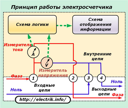
Electric energy meters are divided into two large groups operating in networks:
1. AC voltage of industrial frequency;
2. DC current.
The first category of these devices is the most numerous. With her, we begin a brief overview of a variety of models.
AC power meters
This class of counters by design is divided into three types:
1. induction, working since the end of the nineteenth century;
2. electronic devices that appeared not so long ago;
3. hybrid products that combine digital technology with an induction or electrical measuring part and a mechanical metering device in their design.
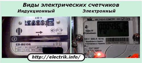
Induction metering devices
The principle of operation of such a counter is based on the interaction of magnetic fields. created by electromagnets of a current coil embedded in the load circuit, and a voltage coil connected in parallel to the supply voltage circuit.
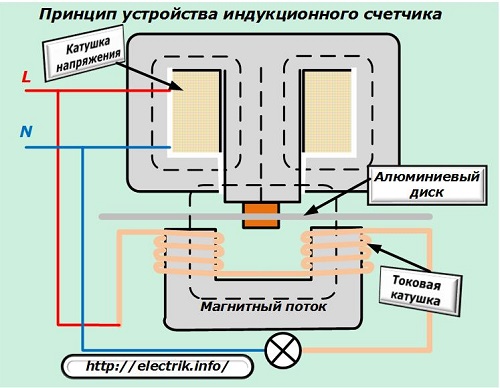
They create a total magnetic flux proportional to the value of the power passing through the meter. In the field of its action is a thin aluminum disk mounted in a rotation bearing. It reacts to the magnitude and direction of the created force field and rotates around its own axis.
The speed and direction of movement of this disk correspond to the value of the applied power. A kinematic scheme is connected to it, consisting of a system of gears and wheels with digital indicators that indicate the number of completed revolutions, acting as a simple counting mechanism.
Single-phase induction meter, device features
The design of the most common induction meter, designed for a single-phase AC power supply network, is shown in an unassembled form in the picture, consisting of two combined photographs.
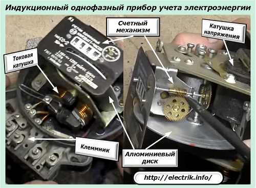
All the main technological units are indicated by pointers, and the electrical diagram of the internal connections, input and output circuits is shown in the following picture.
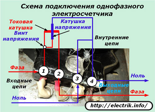
The voltage screw installed under the cover must always be tightened during meter operation. It is used only by employees of electrical laboratories when performing special technological operations - checking the device.
About the device, the principle of operation and features of the operation of electric meters were previously described here:
How to connect the electricity meter correctly
How to take readings from an electricity meter
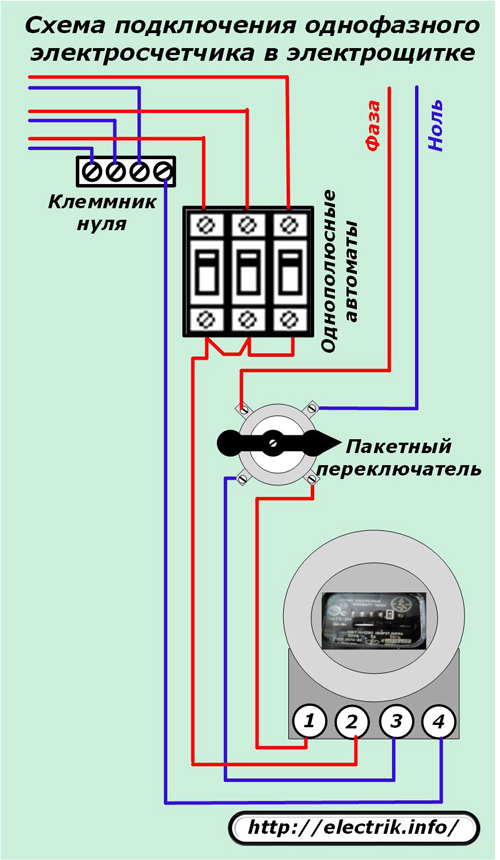
Electric induction meters of this type successfully modify their resource in residential buildings and people's apartments. They are connected in switchboards according to the standard scheme through single-pole circuit breakers and a packet switch.
Design features of a three-phase induction meter
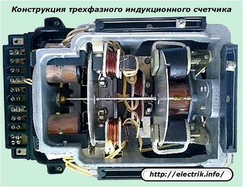
The device of this measuring device is fully consistent with single-phase models, except that the magnetic fields generated by the coils of currents and voltages of all three phases of the power circuit power circuit participate in the formation of the total magnetic flux affecting the rotation of the aluminum disk.
Due to this, the number of parts inside the case is increased, and they are denser. The aluminum disk is also doubled. The connection scheme for current and voltage coils is performed according to the previous connection option, but taking into account the summation of magnetic fluxes from each individual one.
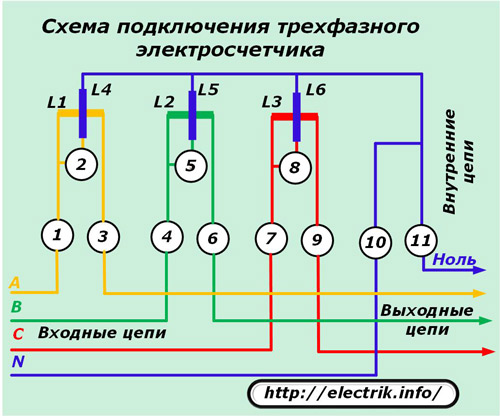
The same effect can be achieved if instead of one three-phase meter, single-phase devices are included in each phase of the system. However, in this case, you will need to deal with adding their results manually. In a three-phase induction meter, this operation is automatically performed by one counting mechanism.
Three-phase induction meters can be performed in two types for connection:
1. immediately to power circuits, the power of which must be taken into account;
2. through intermediate voltage and current measuring transformers.
The devices of the first type are used in 0.4 kV power circuits with loads that cannot cause harm to the meter with their small amount of damage. They work in garages, small workshops, private homes and are called direct connection meters.
The circuit diagram of the electrical circuits of such a device in the switchboard is shown in the next picture.
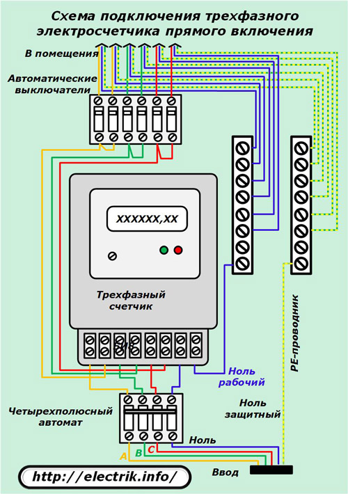
All other induction metering devices work directly through measuring current or voltage transformers separately, depending on the specific conditions of the power supply system, or with their joint use.
The appearance of the panel of the old induction meter of a similar type (SAZU-IT) is shown in the photograph.
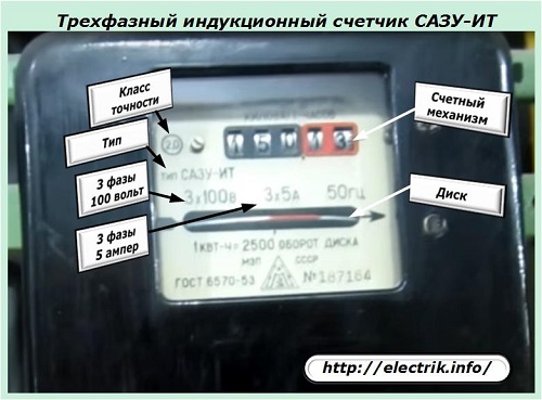
It works in secondary circuits with measuring current transformers of a nominal value of 5 amperes and voltage transformers — 100 volts between phases.
The letter "A" in the name of the type of device "SAZU" means that the device is designed to account for the active component of the total power. Measurements of the reactive component involved in other types of devices, incorporating the letter "P". They are indicated by the type "SRZU-IT".
The above example with the designation of three-phase induction meters indicates that their design cannot take into account the amount of total power spent on the work. To determine its value, it is necessary to take readings from active and reactive energy meters and perform mathematical calculations according to prepared tables or formulas.
This process requires the participation of a large number of people, does not exclude frequent mistakes, and is laborious. New technologies and metering devices working on semiconductor elements save him from carrying it out.
Old induction meters have almost ceased to be produced on an industrial scale. They simply modify their resource as part of working electrical equipment. They are no longer used at newly installed and put into operation complexes, but new, modern models are being installed.
Electronic metering devices
To replace the induction type meters, many electronic devices are now being produced, designed to work in a household network or as part of measuring complexes of complex industrial equipment that consumes enormous power.
In their work, they constantly analyze the state of the active and reactive components of full power based on vector diagrams of currents and voltages. Using them, the total power is calculated, and all values are recorded in the memory of the device. From it you can view this data at the right time.
Two types of common electronic accounting systems
By the type of measurement of composite input values, electronic-type meters produce:
-
with built-in measuring transformers of current and voltage;
-
with measuring sensors.
Devices with integrated measuring transformers
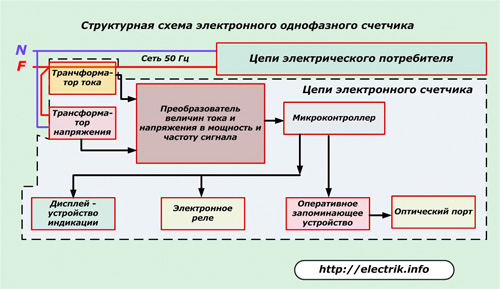
The basic structural diagram of an electronic single-phase meter is shown in the picture.
The microcontroller processes the signals from the current and voltage transformers through the converter and issues the appropriate commands to:
-
display with information display;
-
electronic relay switching the internal circuit;
-
RAM RAM, which has an information connection with an optical port for transmitting technical parameters through communication channels.
Devices with integrated sensors
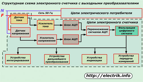
This is another design of the electronic meter. Her circuit works on the basis of sensors:
-
current, consisting of an ordinary shunt through which the entire load of the power circuit flows;
-
voltage operating on the principle of a simple divider.
The current and voltage signals coming from these sensors are very small. Therefore, they are amplified by a special device based on a high-precision electronic circuit and fed to amplitude-digital conversion units. After them, the signals are multiplied, filtered and output to the appropriate devices for integration, indication, conversion and further transmission to various users.
Counters working on this principle have a slightly lower accuracy class, but they fully comply with technical standards and requirements.
The principle of using current and voltage sensors instead of measuring transformers makes it possible to create metering devices for circuits of not only alternating but also direct current, which greatly expands their operational capabilities.
On this basis, meter designs began to appear that can be used in both types of DC and AC power supply systems.
Tariff of modern metering devices
Due to the possibility of programming the operation algorithm, the electronic meter can take into account the power consumption by time of day. This creates the interest of the population to reduce electricity consumption during the most intense peak hours and thereby unload the load created for energy supplying organizations.
Among electronic metering devices there are models that have different capabilities of the tariff system. The greatest abilities are possessed by meters, which allow flexible reprogramming of the metering device for changing tariffs of electric networks taking into account the time of year, holidays, various discounts on weekends.
The operation of electricity meters in accordance with the tariff system is beneficial for consumers - money is saved for paying for electricity and for supplying organizations - peak load is reduced.
See also on this topic:
How is the electronic electricity meter arranged and working
Design features of industrial metering devices for high voltage circuits
As an example of such a device, consider the Belarusian counter brand Gran-Electro SS-301.
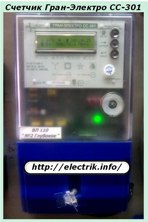
It has many useful functions for users. Like ordinary household metering devices, it is sealed and periodically calibrated.
Inside the case there are no movable mechanical elements. All work is based on the use of electronic boards and microprocessor technologies. Measuring transformers are engaged in the processing of input current signals.
These devices pay particular attention to reliability and information security protection. In order to preserve it, it is introduced:
1. two-level system for sealing internal boards;
2. five-level scheme of organization of access to passwords.
The filling system is carried out in two stages:
1. access to the body of this meter is immediately limited at the factory after completion of its technical tests and completion of state verification with the registration of the protocol;
2. Access to connecting wires to the terminals is blocked by representatives of the energy supervision or the energy supply company.
Moreover, in the operation algorithm of the device there is a technological operation that fixes in the electronic memory of the device all the events associated with the removal and installation of the terminal block cover with exact binding by date and time.
Password Access Control Scheme
The system allows to differentiate the rights of users of the device, to separate them according to the access to the meter settings by creating levels:
-
zero, providing removal of restrictions on viewing data locally or remotely, time synchronization, correction of indications. The right is granted to authorized users of the device;
-
the first, which allows you to set up equipment at the installation site and record settings of operating parameters that do not affect the characteristics of commercial use in RAM;
-
the second, allowing access to the information of the device to representatives of energy supervision after its adjustment and preparation for commissioning;
-
the third one, which gives the right to remove and install the cover from the terminal block for access to the terminals or the optical port;
-
fourth, providing for the ability to access the device boards for installing or replacing hardware keys, removing all seals, performing work with the optical port, upgrading the configuration, calibrating correction factors.
Ways to connect industrial meters in energy enterprises
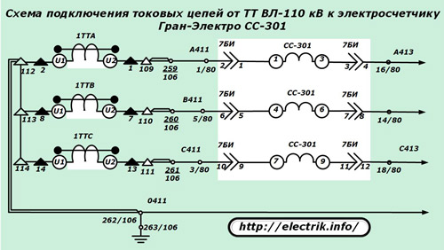
For the operation of metering devices, branched secondary circuits of measuring chains are created through the use of high-precision current and voltage transformers.
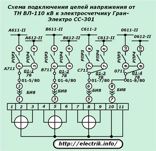
A small fragment of such a circuit for the current circuits of the Gran-Electro SS-301 meter is shown in the picture. It is taken from the working documentation.
For the same meter, a fragment of connecting voltage circuits is shown below.
Combining metering devices into a unified system of automated metering and control system
The system of automated control and metering of electric energy began to actively develop thanks to the capabilities of electronic meters and the development of methods for remote transmission of information. To connect the metering devices of the induction system, special sensors are developed.
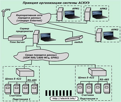
The main objective of the ASKUE system is the rapid collection of information in a single control center. At the same time, it receives data streams from all consumers of existing substations. They contain information on the issues of consumed and released capacity with the possibility of analyzing methods for its generation and distribution, calculating cost and accounting for economic indicators.
To solve the organizational issues of the ASKUE system, it is provided:
-
installation of high-precision metering devices in places of electricity metering;
-
information transfer from them is performed by digital signals using “adders” having random access memory;
-
organization of a communication system over wired and radio channels;
-
implementation of the processing scheme of the received information.
DC electricity meters
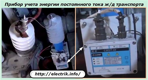
Models of meters of this class record energy in different technological modes, but most often they are used on equipment of electric rolling stock of urban transport and on railways.
They are created on the basis of an electrodynamic system.
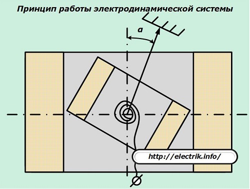
The main principle of operation of such counters is the interaction of the forces of magnetic flux formed by two coils:
1. the first is fixed permanently;
2. the second has the ability to rotate under the influence of magnetic flux, the magnitude of which is proportionally dependent on the value of the current flowing along the circuit.
The rotation parameters of the coil are transmitted to the counting mechanism and are taken into account by the consumption of electrical energy.
See also: Ways to save electricity in an apartment and a private house
See also at bgv.electricianexp.com
:

