Categories: How does it work
Number of views: 107079
Comments on the article: 4
How is the electronic electricity meter arranged and working
The main purpose of this device is to constantly measure the power consumption of the monitored section of the electrical circuit and display its magnitude in a human-friendly form. The element base uses solid state electronic components operating on semiconductors or microprocessor designs.
Such devices are produced for working with current circuits:
1. constant value;
2. sinusoidal harmonic shape.
DC electricity meters only work at industrial enterprises that operate powerful equipment with high consumption of constant power (electrified railway transport, electric cars ...). For domestic purposes, they are not used, are issued in limited quantities. Therefore, in the further material of this article we will not consider them, although the principle of their operation differs from models operating on alternating current, mainly by the design of current and voltage sensors.
Electronic AC power meters are manufactured to account for the energy of electrical devices:
1.with a single-phase voltage system;
2. in three-phase circuits.
Electronic meter design
The entire element base is located inside the housing, equipped with:
-
terminal block for connecting electrical wires;
-
LCD panel;
-
operating controls and transmitting information from the device;
-
measuring transformers;
-
printed circuit board with solid-state elements;
-
protective cover.
Appearance and the main user settings of one of the many models of similar devices produced at the enterprises of the Republic of Belarus are presented in the picture.
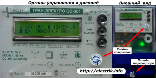
The performance of such electric meter confirmed by:
-
the stamp of the verifier confirming the passage of the metrological verification of the device on the test bench and the assessment of its characteristics within the accuracy class declared by the manufacturer;
-
undisturbed seal of the energy supervision company responsible for the correct connection of the meter to the electrical circuit.
Interior view boards of a similar device is shown in the picture.
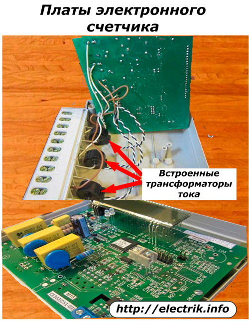
There are no moving and induction mechanisms. And the presence of three built-in current transformers, used as sensors with the same number of clearly visible channels on the circuit board, indicate a three-phase operation of this device.
Electrotechnical processes taken into account by an electronic meter
The work of internal algorithms of three-phase or single-phase structures occurs according to the same laws, except that in a 3-phase, more complex device, a geometric summation of the values of each of the three component channels occurs.
Therefore, the principles of operation of the electronic meter will mainly be considered on the example of a single-phase model. To do this, recall the basic laws of electrical engineering related to power.
Its full value is determined by the components:
-
active;
-
reactive (sum of inductive and capacitive loads).
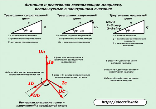
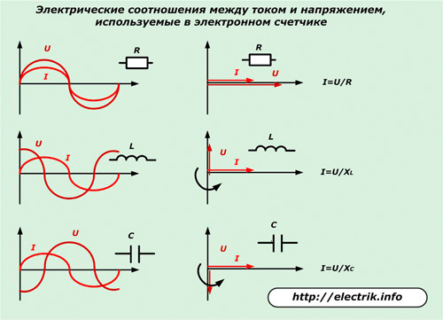
The current flowing through the common circuit of a single-phase network is the same in all areas, and the voltage drop at each of its elements depends on the type of resistance and its magnitude. On the active resistance, it coincides with the vector of the passing current in the direction, and on the reactance it deviates to the side. Moreover, in inductance, it is ahead of the current in angle, and lags behind in capacitance.
Electronic meters are able to take into account and display the total power and its active and reactive value. For this purpose, current vectors with voltage supplied to its input are measured.The value of the deviation of the angle between these incoming values determines and calculates the nature of the load, provides information about all its components.
In different designs of electronic meters, the set of functions is not the same and can significantly differ in their purpose. By this, they radically stand out from their induction analogues, which work on the basis of the interaction of electromagnetic fields and induction forces that cause the rotation of a thin aluminum disk. Structurally, they can only measure active or reactive power in a single-phase or three-phase circuit, and the full value - you have to calculate separately manually.
The principle of measuring power by an electronic meter
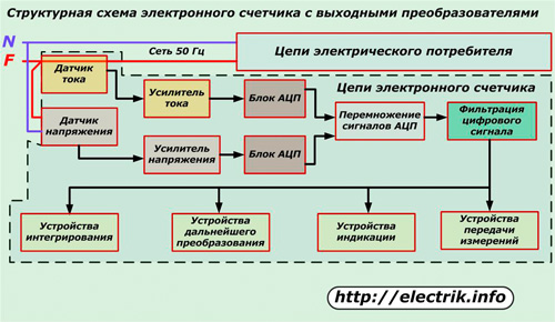
Scheme of operation of a simple metering device with output converters shown in the figure.
It uses simple sensors to measure power:
-
current based on a conventional shunt through which the phase of the circuit passes;
-
voltage operating according to the scheme of a well-known divider.
The signal recorded by such sensors is small and is increased with the help of electronic amplifiers of current and voltage, after which analog-digital processing takes place for further conversion of the signals and their multiplication in order to obtain a value proportional to the value of power consumption.
Next, the digitized signal is filtered and output to devices:
-
indication;
-
integration;
-
transmission of measurements;
-
further conversion.
The input sensors of electrical quantities used in this circuit do not provide measurements with a high accuracy class of current and voltage vectors, and, accordingly, the calculation of power. This function is better implemented by measuring transformers.
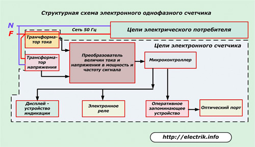
Single-phase electronic meter operation diagram
In it, the measuring CT is included in the gap of the consumer phase wire, and the VT is connected to phase and zero.
The signals from both transformers do not need amplification and are sent through their channels to the ADC unit, which converts them into a digital power and frequency code. Further conversions are performed by a microcontroller that controls:
-
display
-
electronic relay;
-
RAM - random access memory.
Through RAM, the output signal can be transmitted further to the information channel, for example, using an optical port.
Functionality of electronic meters
The low power measurement error estimated by the accuracy class of 0.5 S or 02 S allows the use of these devices for the purpose of commercial metering of used electricity.
Designs designed for measurements in three-phase circuits can operate in three or four-wire electrical circuits.
The electronic meter can be directly connected to existing equipment or have a design that allows the use of intermediate, for example, high-voltage measuring transformers. In the latter case, as a rule, an automatic conversion of the measured secondary quantities into primary values of current, voltage, and power, including the active and reactive components, is performed.
The counter captures the direction of full power with all its components in the forward and reverse directions, stores this information in relation to time. In this case, the user can take energy readings by its increment for a certain period of time, for example, current or selected from the calendar day, month or year, or - accumulation for a certain appointed time.
Fixing the values of active and reactive power for a certain period, for example, 3 or 30 minutes, as well as the quick call of its maximum values for a month greatly facilitates the analysis of the operation of power equipment.
At any time, you can view instant indicators of active and reactive consumption, current voltage, frequencies in each phase.
The presence of the multi-tariff energy metering function using several information transmission channels expands the conditions of commercial use. At the same time, tariffs are created for a certain time, for example, every half hour of a weekend or a working day by season or month of the year.
For the convenience of the user, the display shows the operating menu, between the items of which you can navigate using the adjacent controls.
An electronic energy meter allows not only to read information directly from the display, but also to view it through a remote computer, as well as to enter additional data or program them through the optical port.
Protection of information
Installation of seals The counter is made in two stages:
1. at the first level, access to the device’s body is prohibited by the technical control service of the plant after the meter has been manufactured and passed state verification;
2. at the second sealing level, access to the terminals and connected wires is blocked by a representative of the energy supplying organization or energy supervision.
All events of removal and installation of the cover are equipped with an alarm system, the operation of which is recorded in the memory of the event log with reference to time and date.
Password system provides for restricting users to access information and may contain up to five restrictions.
Level zero completely removes restrictions and allows you to view all data locally or remotely, synchronize time, adjust readings.
First level additional access password is provided to employees of the installation or operational organization ASKUE systems for setting up equipment and recording parameters that do not affect commercial characteristics.
Second level The main access password is assigned by the responsible energy supervision employee at the meter that has been set up and is fully prepared for work.
Third level primary access is given to energy supervision workers who remove and install the cover from the meter to access its terminal clamps or conduct remote operations through the optical port.
Fourth level provides the ability to install hardware keys on the board, remove all installed seals and the ability to work through the optical port to improve configuration, replace calibration coefficients.
The above list of possibilities that an electronic electricity meter possesses is a general overview. It can be set individually and differ even on each model of the same manufacturer.
See also at bgv.electricianexp.com
:

