Categories: Featured Articles » Electrician at home
Number of views: 32931
Comments on the article: 2
Installing and connecting an electricity meter: how to connect correctly
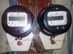 The metering of consumed electricity is carried out by measuring instruments that take into account the power passing through them for the estimated period of time.
How does an electricity meter work?
To properly install and connect electric meter it is necessary to understand the principle of its work, which consists in constantly monitoring parameters such as:
1. the magnitude of the load flowing through the measuring current body;
2. the value of the voltage supplied to the input of the controlled electrical circuit;
3. connection time.
Any electric meter, regardless of its design, has:
1. terminal block to which electricity is supplied and simultaneously removed (input and output circuits);
2. The internal circuit.
When connecting wires to terminal block It is important not only to switch the phase and zero conductors to their places, but also to observe the polarity: incoming and outgoing circuits determine the direction of currents in the internal circuit of the counter, affect the final result of the information display.
The interior of any electric meter can be arbitrarily represented by the following components:
-
current measuring body;
-
voltage measuring body;
-
internal logic circuitry;
-
digital display or mechanical display device.
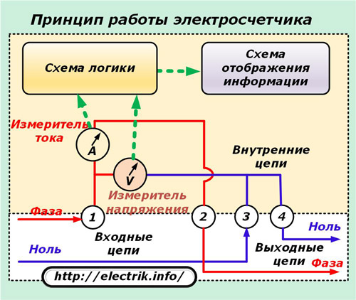
Current and voltage meters are usually made by specially wound coils from which electrical signals are proportional to the magnitude of the vectors passing through them with a certain accuracy class.
Information from the meters is fed to the logical part, where it is processed by constantly multiplying the instantaneous values of the secondary current vectors of voltage and voltage, and then sent to the display for reading by the user.
Since when multiplying the current vector by voltage, the value of the consumed instantaneous power is obtained, and perfect work is necessary to fix, the time the meter is under load automatically takes this factor into account. As a result, the measurement is counted in kilowatt hours consumed.
Read more about the device of modern meters here: How is the electronic electricity meter arranged and working
Any measuring device, including an electric meter, works in a certain accuracy class. This value is always indicated on the front panel.
Connecting and disconnecting the electric meter is carried out by electricians of energy supplying organizations, which have the right to independently carry out this operation and are obliged to close the places for connecting wires with special covers with the subsequent installation of their seals on them.
A variant of sealing an old but still working single-phase electric meter of the С0-2М series is shown in the photograph.
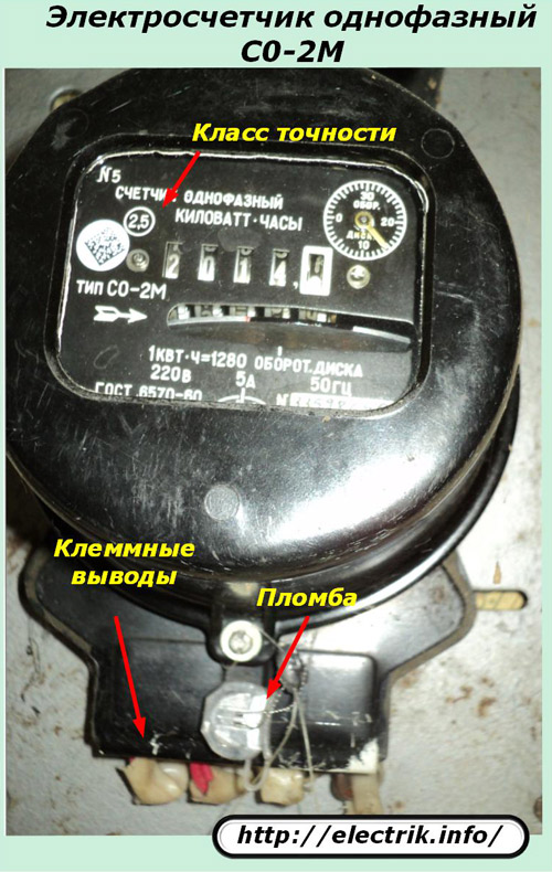
The presence of such a seal indicates that the electrician who carried out the seal is responsible for the correct connection and operability of the circuit. If it is violated after the device is put into operation, the owner of the premises is subject to penalties.
How to connect a single-phase electricity meter
Manufacturers of electrical equipment have long had the practice of depicting a circuit for switching wires to their products, not only in the technical documentation, but also directly on the body of their products.
An example of such a designation with reference to the terminal board of the above counter is shown in the next picture, where the current and voltage coils are usually denoted by simple thickened lines. For clarity, they are highlighted in red and blue.
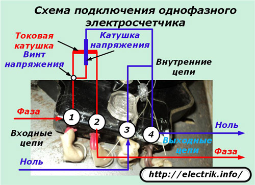
The numbering of the terminals corresponds to the real marking 1, 2, 3, 4. Near the terminal of a suitable phase wire in many designs there is a voltage screw. It is used during metrological checks of the device and must be screwed in as far as it will go. Otherwise, the voltage coil circuit will be taken out of operation, and the counter will begin to read incorrect readings.
Wiring diagram for a single-phase electric meter in an apartment electrical panel
Now many old buildings are still in operation, in which electric meters of induction type work. For them, specially designed shields were placed on the stairwell of the entrance or entrance to the apartment, which were supplied with:
1. packet switch;
2. single-phase electric meter;
3. a set of unipolar automatic switches;
4. terminal blocks for connecting wires.
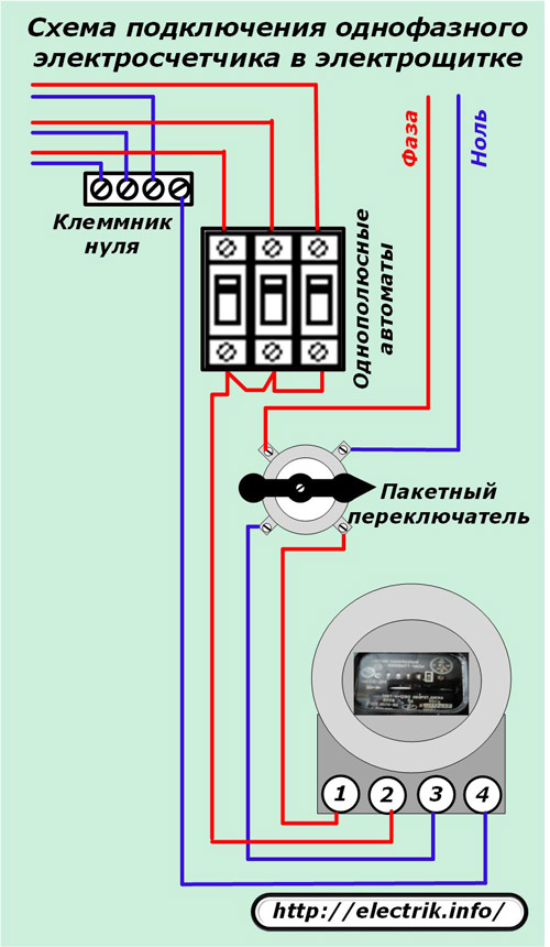
On the packet switch (you can use a two-pole circuit breaker instead), the phase and zero of the electrical circuit of a building equipped with electrical wiring by TN-C system (without protective zero). This switch in one position delivers both potentials to the electric meter, and in the other, it breaks, removing stresses from the entire electrical circuit.
This is the only place in home wiring where a working zero gap is created. Other cases of rupture should not be created anywhere, as the picture shows.
Always circuit breakers break only phase. It comes from the output terminal No. 2 of the meter through a common jumper to the inputs of the circuit breakers and leaves them through the cables to power the power circuits and fixtures of the room.
The working zero after the counter goes to its own terminal strip, where the corresponding wire conductors are collected, leaving the rooms via cables.
How to connect a three-phase electricity meter
In order to correctly connect the electrical wires, it is necessary to present the principle of operation of an electric meter of this design, which is based on the circuit of the previous analogue.
The principle of operation of a three-phase electric meter
The presence of three phases in the wiring requires a total metering of the consumed electricity in each circuit. For this purpose, three circuits are introduced into the design that control the power in each of their circuits with the same current and voltage meters.
They are presented in the picture in different shades. The current flow pattern in phase C is highlighted in red, B in green and A in yellow.
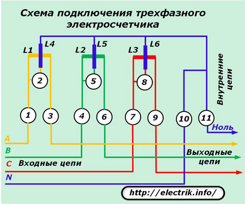
Accordingly, current coils are marked in the same color and marked with L1, L2, L3. The voltage coils are highlighted in blue and labeled L4, L5. L6. All this, the measuring organs analyze the signals passing through them and transmit information for processing by the comparison body and display on the scoreboard with their secondary values.
Connection diagram for a three-phase direct-acting meter
In home wiring, a three-phase 0.4 kV network with a grounded neutral is used. Typically, the load currents correspond to the ratings of current coils, do not exceed their values.
This allows current to pass through the meter’s internal lines without the use of additional step-down transformers. In addition, the voltage circuits also correspond to the calculated class for the coils of their measuring organs.
Due to these features, it is possible to connect the electric meter directly by inserting it into the circuit without using any intermediate elements.
The option of directly connecting a three-phase electric meter to a five-wire wiring is shown in the next picture.
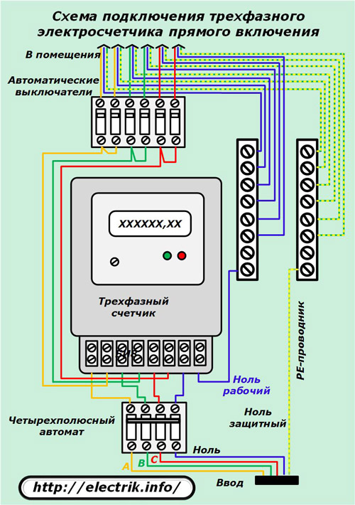
Four potential conductors of phases A, B, C and working zero N come from the input cable to the four-pole circuit breaker. All of them can be torn by this machine to completely relieve voltage from consumers. This is done:
-
manually by the operator;
-
current protections in automatic mode.
From the output terminals of the machine, the phases are fed to the corresponding terminals of the meter, marked with the numbers 1, 4, 7, 10 and left from the terminals 3, 6, 9, 11. At the direct-on meter, the terminals 2, 5, 8 are hidden inside the housing and are not accessible for connecting wires .
The potential of the phases by the corresponding jumpers after the counter is routed to the individual circuit breakers of the room power supply chains. The working zero, as in the single-phase meter circuit, enters the room power cables through its own terminal block.
The protective PE conductor is not torn anywhere. It immediately connects from the input cable to its own terminal block and is wired from it with wires through cables to all rooms.
When performing work in the measuring circuits of any electric meter, maximum attention and caution must be exercised. This is a dangerous and technically difficult job, which electricians with an electrical safety group of at least III and successfully passed special training are allowed to independently perform.
See also at bgv.electricianexp.com
:
