Thyristor power controllers. Circuits with two thyristors
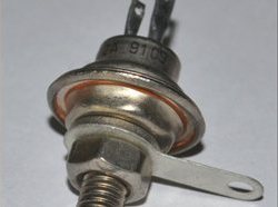 Somewhat better results are obtained using circuits using two thyristors connected in opposite directions - in parallel: there is no need for extra diodes, and thyristors are easier to operate. Such a circuit is shown in the figure.
The control pulses for each thyristor are generated separately by the circuit on the dynistors V3, V4 and capacitors C1, C2. The power in the load is regulated by a variable resistor R5.
But two thyristors are also impermissible luxury. Therefore, the electronic industry has mastered the production of triacs, or, as they are otherwise called symmetrical thyristors. With the dimensions and shape of the case, the triac is similar to a conventional thyristor, only two thyristors “live” inside it, connected in the same way as thyristors V1 and V2 are connected in the figure. In this case, the triac has only one control electrode ...
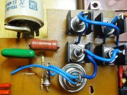 Thyristor power controllers are one of the most common amateur radio designs, and this is not surprising. After all, everyone who has ever used an ordinary 25 - 40 watt soldering iron, its ability to overheat is even very well known. The soldering iron begins to smoke and hiss, then, soon enough, the tinned sting burns out, turns black. Soldering with such a soldering iron is already completely impossible.
And here the power regulator comes to the rescue, with the help of which you can set the temperature for soldering quite accurately. It should be guided by the fact that when a soldering iron touches a piece of rosin, it smokes well, so, medium, without hissing and splashing, not very vigorously. You should focus on the fact that the soldering is contour, shiny. Of course, modern soldering stations are equipped with thermally stabilized soldering irons, digital displays and heating temperature control ...
Photo relay schemes for lighting control
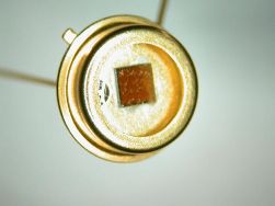 One of the tasks performed with the help of photosensors is lighting control. Such schemes are called photorelay, most often it is a simple inclusion of lighting in the dark. For this purpose, a lot of circuits were developed by ham radio operators, here are some of them.
Probably the simplest diagram is shown in the figure. The number of parts in it is small, it will not work less, and the efficiency, read the sensitivity, is quite high.
This is achieved by the fact that the transistors VT1 and VT2 are connected according to a composite transistor circuit, also called a Darlington circuit. With this inclusion, the gain is equal to the product of the gain of the components of the transistors. In addition, such a circuit provides a high input impedance, which allows you to connect high-impedance signal sources, as shown in the circuit ...
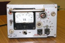 A modern motorist is armed with all the benefits of technological progress and most of us no longer remember how to inflate a tire with a hand-held automobile pump or apply and vulcanize a rubber patch on a car camera.
We equalize the pressure in the wheels with a compressor, we clean the interior with a vacuum cleaner, and instead of a lever bent by the letter “si”, we drive the jack with a screwdriver with a metal hook clamped into the cartridge. But all the countless electric assistants of the motorist eat electricity, so we strain our car in the garage, forcing it to work for a long time on the cigarette lighter socket to the detriment of the environment and our wallet.
Need a garage power supply: +12 volts, powerful, simple, reliable, safe and versatile. +12 volts (and preferably 12 - 15 volts) - the voltage of the vehicle's on-board network and the operating voltage of its countless accessories ...
Feedback Operational Amplifier Circuits
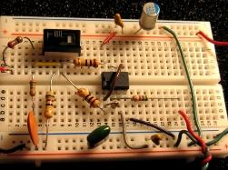 At the end of the article “An ideal operational amplifier”, it was shown that when using an operational amplifier in various switching circuits, the amplification of the cascade on a single operational amplifier (OA) depends only on the feedback depth. Therefore, in the formulas to determine the gain of a particular circuit, the gain of the “bare” op-amp, so to speak, is not used. That is just that huge coefficient which is specified in directories.
Then it’s quite appropriate to ask the question: “If the final result (gain) does not depend on this huge“ reference ”coefficient, then what is the difference between the opamp with amplification several thousand times, and with the same opamp, but with amplification several hundred thousand and even millions? ” The answer is quite simple. And in both cases the result will be the same, the amplification of the cascade will be determined by the elements of the environmental protection system, but in the second case ...
Feedback operational amplifier circuitry
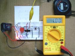 If you use an operational amplifier without negative feedback (OOS), then we can definitely say that we get a comparator. In order to understand how it works, you can do some simple, but visual experiments. To do this, you need a little: the operational amplifier itself, a power supply with a voltage of 9 ... 25V, several resistors, a pair of LEDs and a voltmeter (digital multimeter).
The simplest logic probe is assembled from LEDs and resistors. When a positive voltage is applied to the probe input (you can even supply + U), the red LED lights up, and if the input is connected to a common wire, the green one lights up. With the help of such a probe, the output state of the tested operational amplifier becomes clear and understandable. As an experimental "rabbit" any "Rabbit" is suitable for any, not very high quality and expensive...
Operational amplifiers. Part 2. The perfect operational amplifier
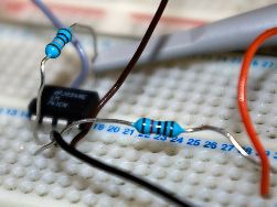 To better understand the principles of constructing circuits using operational amplifiers, they often use the concept of an ideal operational amplifier. What is its ideality, its wonderful properties? There are not so many of them, but they all tend either to zero, or even to infinity. But this is how an operational amplifier behaves that is not covered by feedback (OS) and generally does not have any external connections.
In this article we will try to talk about feedback and some schemes for including operational amplifiers without mentioning cumbersome mathematical formulas with integrals. But some, very simple and understandable, at the eighth grade level of the school, which will help to understand the general meaning, still can not be avoided.
With such a "rampant" gain, it is enough to apply only a few microvolts to its inputs (for example, mains interference) to get a voltage close to the output ...
Operational amplifiers - types, designations, amplifier enclosures
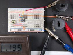 First, a few words about what operational amplifiers (op amps) are. The name itself suggests that some operations are performed with their help. Could it be a surgical instrument? Not at all. This tool is designed to perform various mathematical operations. Initially, operational amplifiers were used in analog computers (AVMs), in which information was represented by continuous signals in the form of currents and voltages.
Although AVMs are now a thing of the past, analog signals received from various sensors (for example, fluid pressure or the angle of the gas pedal) are still used very widely. And there’s simply nowhere to go from this. Most often, analog signals are converted to digital using, for example, an ADC, and their further processing is performed digitally using microprocessors or microcontrollers ...
