Categories: Featured Articles » Practical Electronics
Number of views: 73841
Comments on the article: 4
Garage power supply
 A modern motorist is armed with all the benefits of technological progress and most of us no longer remember how to inflate a tire with a hand-held automobile pump or apply and vulcanize a rubber patch on a car camera.
We equalize the pressure in the wheels with a compressor, we clean the interior with a vacuum cleaner, and instead of a lever bent by the letter “si”, we drive the jack with a screwdriver with a metal hook clamped into the cartridge. But all the countless electric assistants of the motorist eat electricity, so we strain our car in the garage, forcing it to work for a long time on the cigarette lighter socket to the detriment of the environment and our wallet. We need a garage power supply!
Need a garage power supply: +12 volts, powerful, simple, reliable, safe and versatile.
- +12 volts (and preferably 12 - 15 volts) - the voltage of the vehicle's electrical system and the operating voltage of its countless accessories;
- powerful - the power of such a unit should be enough to connect the most powerful garage consumers and to recharge the battery;
- simple - the main thing here is the simplicity of manufacture, because we are talking about the self-made design of a motorist, not an electronics engineer, moved on microcontrollers and SMD;
- safe operation - words that speak for themselves. The load must be galvanically separated from the mains (not the UPS, but the old tested transformer power supply);
- universality - this property of a garage power supply suggests that loads calculated on the cigarette lighter socket, on the backlight connector (in domestic cars), on crocodiles and so on should be equally conveniently connected to it.
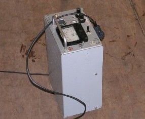
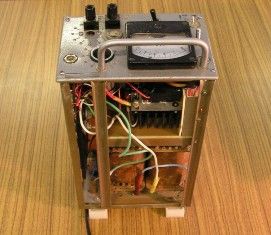
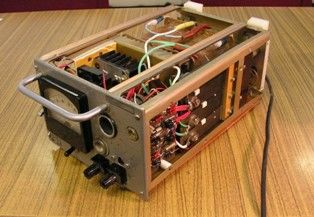
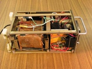
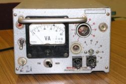
The photo shows power supply for garage meeting all these requirements. The remains of some electronic unit of unknown purpose are used as a rigid frame. Manufacturers carefully carved in its front panel a lot of holes of various sizes, which are perfect for installing a measuring device, indicator LEDs, toggle switches and an adjustment resistor.
The metal bracket above the ampervoltmeter is great for carrying. Two sets of support legs of the device allow you to work with the power supply in both vertical and horizontal position. The top cover of the power supply is cut from a sheet of metal and painted.
The lower toggle switch on the left is the network one.
Upper toggle switch on the left - load connection.
The toggle switch under the measuring head - switching the operating modes of the device: ammeter-voltmeter.
The red LED on the top left indicates the output voltage, and the top right green indicates the mains voltage.
The load can be connected to the cigarette lighter socket, to the backlight socket, with plugs to the lower connector, or to it with wires for a clip. Uout = 3 - 15 volts, Iout = 8A
In order to be able to connect not only ordinary consumers such as a local backlight to the power supply unit, but also to check smart devices like GPS navigators or DVRs, the unit circuit is slightly complicated and is a powerful parametric stabilizer.
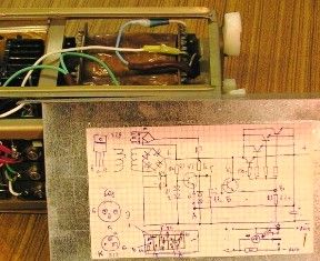
The classic circuit of a parametric stabilizer on a composite output transistor with short circuit protection.
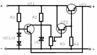
This is the easiest and most successful. circuit suitable for garage power supply. It is very tenacious, it will not be damaged either by accidental closure of the output contacts, or by reverse polarity of the load like a battery. When a short circuit is removed, the circuit will continue to operate.
You can use almost any transistor of the corresponding polarity in the power supply and only its load capacity will depend on it (moreover, if you change the polarity of ALL transistors, swap + and -, the anodes and cathodes of ALL diodes and a zener diode, then the unit will work just as well )
A printed circuit board can not be made because of its primitiveness, but to assemble the circuit by mounting it on the surface. In a word, it all depends on the capabilities and desire of the motorist.
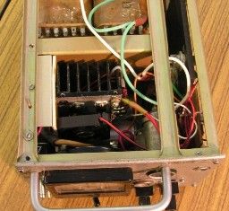
In the proposed design, such a circuit is assembled, in the output stage it is parallel to four domestic KT829 transistors and, to increase the stability of Uout, the circuit for generating the reference voltage (VD1, VD2, VT1) is powered by a separate transformer winding.
The transformer perfectly fit into the design of the power supply for the garage - the “old acquaintance” TSA-270-1 (the letter A in the name indicates that an aluminum wire was used for the windings). You can not rewind it, when using windings 8-18 and 8'-18 'in a parallel connection, the power supply unit without overloads supplies the compressor for a long time (at the same time, the measuring device in the "ammeter" mode rolls over, that is, a current of more than five amperes is transferred to the load )
In order to independently assemble such a power supply unit, you need to find a transformer, not necessarily exactly the same as in the proposed design (it may have to be rewound in this case), several non-deficient parts, and all this should be placed in any suitable case with terminals. The measuring device can not be installed, but control the voltage parameters using an external multimeter.
It is very convenient to work with such a garage power supply unit - the battery does not sit down, you do not need to start the engine for recharging and open the garage for ventilation, you can check the performance of any car devices or set up a motor vehicle design. With it, a dead battery can be easily recharged, just don’t try to use the power supply as a starting device - it will certainly burn.
Case study:
- on the car it was necessary to replace the battery and at the same time save the settings of the electronic control unit and all systems of the car. The power supply was connected in parallel with the battery using the “cigarette-lighter” wires and calmly held the on-board network while the old battery was being replaced with a new one.
Notes on the design of the power supply for the garage:
- the photo shows a 60-mm computer fan for blowing a radiator with output transistors, practice has shown that it is quite possible to do without it;
- calculation of shunts and calibration of the device was done manually in advance, did not get there - the current given by the unit turned out to be higher than the calculated one. It is planned to put a shunt at 5 amperes, then the whole scale will be ten amperes;
- after the photo shoot, which was a long time ago, the transformer windings were rewound: one top was wound and in its place in one layer until the row was filled, a 1.5 mm copper wire was laid, it turned out 46 turns, about 19 volts. In the operation of the unit, nothing has changed, only the output voltage began to sag a little less. Conclusion: rewinding only for any specific purpose, so simple is a waste of time.
Continuation of the article: The electrical circuit of the power supply for the garage
See also:Wiring diagram in the garage - design and installation features
Nikolay Martov
See also at bgv.electricianexp.com
:

