Categories: Featured Articles » Practical Electronics
Number of views: 24176
Comments on the article: 0
Operational amplifiers. Part 2. The perfect operational amplifier
 To better understand the principles of constructing circuits using operational amplifiers, they often use the concept of an ideal operational amplifier. What is its ideality, its wonderful properties? There are not so many of them, but they all tend either to zero, or even to infinity. But behaves like that operational amplifier not covered by feedback (OS) and generally not having any external connections.
In this article we will try to talk about feedback and some schemes for including operational amplifiers without mentioning cumbersome mathematical formulas with integrals. But some, very simple and understandable, at the eighth grade level of the school, which will help to understand the general meaning, still can not be avoided.
Gain
With such a "rampant" gain, it is enough to apply only a few microvolts to its inputs (for example, mains interference) to get an output voltage close to 15V. This state indicates saturation of the output.
It is appropriate to recall the same state in transistors. Naturally, in this form, no gain is obtained at all. Therefore, real operational amplifiers are always covered by negative feedback, which will be discussed below.
Although it should be noted that quite often operational amplifiers are used without feedback, and in some cases with positive feedback. This application is found in comparators - devices for accurate comparison of analog signals. Comparators are available in the form of specialized microcircuits, and are also part of other microcircuits. Just remember the legendary integrated timer NE555, which contains within itself two comparators.
Almost recent history
At one time, the domestic electronic industry also mastered the production of operational amplifiers. The first operational amplifier was K1UT401A (B), subsequently renamed K140UD1 with the same letters at the end. So, being an almost exact copy of the American brother UA702, the analogue with the letter A at a supply voltage of ± 6V had a gain in the range of 500 ... 4500, and with the letter B (± 12V) 1500 ... 13000.
By modern standards, this is just ridiculous, but, nevertheless, these archaic amplifiers can still be found. But even with such "small" gain, it was impossible to do without negative feedback.
And just the appearance of operational amplifiers in integrated design introduced this universal component into industrial, domestic and amateur circuits. After all, you must admit that an operational amplifier with electronic tubes or even a transistor option, except in defense AVMs, could not be used.
Inputs and outputs of operational amplifiers
The operational amplifier has two inputs and one output, and, of course, two outputs for supplying voltage. This is the minimum set of conclusions that is vital. This is exactly how it is with most modern operational amplifiers. Once there were conclusions for connecting elements of frequency correction and balancing.
Power is most often bipolar with a midpoint, which makes it possible to amplify by constant voltage. In this case, it is generally accepted that the frequency range of operational amplifiers starts from 0 Hz, and the upper frequency is limited both by the type of operational amplifier itself, its internal circuit and the type of transistors, and its switching circuit.
The bandwidth of an ideal operational amplifier extends from DC to infinity.Also, speed or slew rate of the output signal tends to infinity. But we will not consider this issue for now.
What enhances the operational amplifier
The output voltage of the operational amplifier is proportional to the voltage difference at its inputs. In this case, the absolute level of the signals, as well as their polarity, do not play a special role. Only the difference matters. And since all the terms in electronics came from the English language, it’s time to remember the word “different”, which means heterogeneous, difference (the dictionary “Multitran”), and the amplifiers of this principle of operation are called differential.
What does not amplify the operational amplifier
Here we can also recall such a wonderful property of operational amplifiers as the attenuation of a common-mode signal: if the same signal is applied to both inputs, it will not be amplified. This is used when applying a signal over long wires: the useful signal has a different phase, while the interference signal at both inputs is the same.
What can be obtained at the output of the operational amplifier
The output impedance of an ideal operational amplifier tends to zero, which theoretically allows you to get an arbitrarily large, just infinite signal at the output. In fact, the output voltage of a real operational amplifier is limited by the voltage of the power sources: if a bipolar supply voltage, for example, ± 15V, then it is simply impossible to obtain +20 or -25 at the output.
This is with regard to amplification of constant voltages. In the case of amplification, for example, a sinusoid at the output, a sinusoid should also be obtained, the amplitude of which does not exceed the supply voltage.
Input and output voltages cannot be higher than the voltage of power sources. For example, when powered by ± 15V, the output voltage is lower by 0.5 ... 1.5V. But some modern microcircuits allow getting equal to the supply voltage at the output and input. This property in datasheets is referred to as Rail-to-Rail, literally as “tire to tire”. When choosing an operational amplifier, you should pay attention to this property.
Input impedance
The input impedance of both inputs of the operational amplifier is very large and is within hundreds of MegaOhm, and in some cases even GigaOhm. For comparison: the above-mentioned K1UT401 had an input impedance of only a few tens of kOhm.
The input impedance, of course, does not reach infinity, like an ideal operational amplifier, but it is still so large that it does not affect the input signal levels. From this we can conclude that no current flows in the inputs. This is one of the main principles used in the calculation and analysis of circuits on operational amplifiers. For now, you just need to remember it.
The last statement relates directly to operational amplifiers. Such a high input impedance is inherent in the operational amplifiers themselves, but the input impedance of various circuits based on it can be much lower. This circumstance should always be remembered. And now, be careful, the story begins about the most important thing.
Negative Feedback (OOS)
OOS is nothing more than a connection between the output and the input, in which part of the output is subtracted from the input signal. Such a connection leads to a decrease in gain. Unlike OOS, there is positive feedback (POS), which conversely sums the input signal with part of the output. Such connections are used not only in electronic technology, but in many other cases, for example, in mechanics. The effect of these feedbacks can be characterized as follows: OOS leads to the stability of the system, positive leads to its instability.
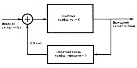
In relation to the operational amplifiers in question, the OOS allows you to set the gain with sufficient accuracy, and also leads to many more qualitative and even pleasant improvements to the circuit. But first you need to figure out how the OOS works.As an example, consider a circuit that can be found in any textbook on automation.
Picture 1.
Ignal U.output signal output. from the output it passes to the summing device (a circle with a plus sign inside) through the OOS circuit with the transfer coefficient β, in this case, less than one. If this coefficient is made greater than unity, which is technically possible, then instead of amplifying the signal, we obtain its attenuation. But for now, we will assume that we need precisely reinforcement.
OOS cliff is just an accident
If you break the feedback loop, then the voltage at the output of the operational amplifier will be U.out. = K * U.in. Theoretically huge value. In fact, it will be limited by the magnitude of the supply voltage. This has already been said earlier. A similar example: if it is an electric motor with stabilization of revolutions (also feedback), then it will simply accelerate as far as possible. In this case, they say that the system went "peddling".
Passing through the circuit of the OOS circuit, the output signal is attenuated by β * U.output. Therefore, only (U.in.-β * U.out.) Comes to the amplifier input through the adder. The minus sign indicates that the feedback is negative. After passing through the device with a gain K, the output will be U.output = K * (U.in.-β * U.out.). In turn, the gain of the entire system K.us. = U.out./U.in. and it turns out that U.out. = K *
After some transformations, one can obtain the following result: K.us. = U.out./U.in. = K * U.in./U.in. * * (1+ K * β) = K / (1+ K * β)
All these transformations led to the simple formula K.us. = K / (1+ K * β). If we assume that K in is large enough (and in the case of using an operational amplifier this is really so), then the unit in brackets will not do much weather, it can be discarded, as a result of which the formula will take the following form:
K.us. = 1 / β
The resulting formula (which, in fact, was the reason why the entire fence of the formulas was pooled) allows us to state that the transfer coefficient of the operational amplifier in the feedback circuit does not in any way depend on the gain of the operational amplifier itself, but is determined only by the feedback circuit parameters , its transmission coefficient β. But, nevertheless, the higher the gain of the operational amplifier itself, the more accurate the specified formula gives, the more stable the circuit works.
Therefore, the amplification cascades on operational amplifiers do not require tuning, as usual transistor cascades: just calculated feedback resistors, soldered, got the required cascade gain. How this is done will be described in the next article.
See also at bgv.electricianexp.com
:

