Categories: Featured Articles » Home automation
Number of views: 73875
Comments on the article: 2
Simple remote control devices for electric receivers by phone
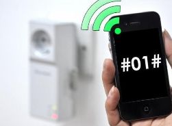 Nowadays, there are already many industrial devices that are controlled by the GSM (Global System for Mobile Communication) standard — a digital standard for mobile communications or a now familiar mobile phone. it security alarm, various control cabinets for industrial equipment, or simply separate sockets, as shown in Figure 1.
The design in appearance is a regular adapter that plugs into a wall outlet. The load can be switched on by ringing or transmitting. sms by mobile phone. It is also possible manual control using two buttons located on the front panel. The power switched by such outlets, depending on the model, is in the range of 1 - 5 kW, which allows you to turn on almost any load.
Multichannel sockets are also produced, like a computer “boot”, which allows you to control the independent operation of several loads. Such devices are one of elements of "smart home"and, therefore, their price is quite high: if you look on the Internet, then prices range from 1000 - 3500 or more rubles.
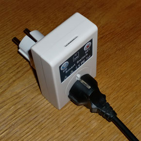
Picture 1. Remote module sms management
For example, a socket with remote control via sms (can be controlled by 5 users) with integrated temperature sensor. Using the sensor, the socket can automatically turn on and off household appliances in accordance with the ambient temperature:
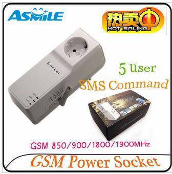
Figure 2 Rsocket with remote sms management
Even more expensive than individual sockets are industrial modules. As an example, Figure 2 shows the offer of an online store for the sale of a DTMF control module.

Figure 3
It was from this picture that the abbreviation DTMF appeared on the surface so far. What is it, see below.
DTMF Signals
In old telephones, dialing was performed by rotating the dial: a finger dialed the spring of the dialer for the required number of digits, the dial spun back to close the contact, and clicks were heard in the handset. Such a set was called pulsed. Pulse dialing was also used in modern devices with a push-button dialer.
Currently used, the so-called tone dialing. Try dialing a number on a landline phone — sounds of different tonality are heard on the receiver. It listens for DTMF signals, - Dual-Tone Multi-Frequency, - a two-tone multi-frequency signal. Figure 4 shows a table by which numbers and some characters are transmitted that are transmitted when dialing a number.
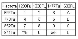
Figure 4
For example, the number “1” corresponds to a combination of frequencies of 697 and 1209 Hz, and the number “9” corresponds to 852 and 1477 Hz. The frequencies are selected so that transmitted together, they do not form harmonics. To decrypt tone packages, there are specialized microcircuits - decoders, for example IL9270N, HM9270, MT8870. These are just analogues of different companies. They may differ even in the number of conclusions, or as now in the foreign manner of pins (from the English pin), but they perform the same functions.
In addition to these specialized decoders, DTMF signals can be decrypted on digital computers using the Goertzel algorithm. Naturally, these signals can also be decoded with the help of microcontrollers or, as they are sometimes called, embedded computers.
In addition to dialing a DTMF phone number, the technology is widely used in smart home systems, alarm and burglar alarms. DTMF tags are also used in commercial broadcasting.
The DTMF system was developed back in 1961, but reached Russia only in the nineties of the last century.At first, tone dialing was provided as a paid service, but not everywhere, since tone dialing is possible only on modern digital telephone exchanges. In general, still in many places antediluvian relay stations are operated, which allow using only pulse dialing.
And now, try to make such an experience: call on the cell, well, at least to your colleague at work, because you are in the same room all day. After he “picks up the phone”, press any numbers on your phone: DTMF signals in the form of short musical sounds will be listened to in the dynamics of his phone. (According to the laws of physics, music is called sounds that have a certain frequency). For example, noise in the street, it is impossible to consider a musical sound.
The same sounds are also present in the dynamics of a telephone headset: the point is small, just connect the DTMF decoder to the headset jack and here you are, a ready-made control device. In some cases, the number of controlled loads is only one, and you need to turn it on or off at any time.
Homemade Remote Devices telephone control
Next, several simple devices will be considered and one of them is simply performed on a relay, and on just one.
A few words about the operation of the circuit. The basis of the device is a polarized relay. As can be seen from the diagram, it has two coils, turned on in such a way that when the voltage is applied to one coil, the relay armature is attracted to one core, and remains in this position even if there is no voltage on the coil anymore - there is a magnet inside the relay.
In order to snap the anchor back, it is necessary to apply voltage, at least a pulse of sufficient duration and amplitude, to another coil. The armature will remain in a drawn state, even when the supply voltage is removed. Doesn't that really remind RS - trigger?
The device is powered from the network through a half-wave rectifier D1, R1, R2, C1. The capacitor C1 produces a voltage of about 24V. Of course, this is done in violation of all safety regulations, but the author assures that if you don’t particularly get impudent and don’t go where you don’t need to, then ... Well, in general everything will work out!
The phone must have a vibrating alert: it is to its contacts that the optocoupler relay IC1 will be connected, in the diagram it is the resistor R4 and the output of the optocoupler 1. The connection polarity is shown in the figure. When connected to a telephone, the polarity of the voltage at the vibration alert should be checked using a multimeter or an LED with a resistor.
When vibro works, the output transistor opens inside the optocoupler (pins 5 and 6). Capacitor C4 is charged from the power source through the right winding of the relay and the open transistor of the optocoupler. The relay arm switches to the left coil, and by contact K1.2 turns on magnetic switchand by contact K1.1 prepares the left coil for the next switchover.
Capacitor C4 discharges through resistor R3 for about five minutes, during which time sending from the phone will not change the device status. With all its obvious simplicity, the device has one significant drawback: the ability to get an exotic polarized relay, and even the necessary passport, is now almost zero. This is written even by the author of the scheme in his description.
Another simple control device is shown in the figure. 5.
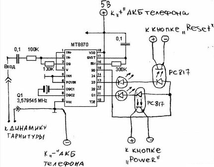
Picture 5. Telephone load control circuit
It is executed on a specialized chip - a signal decoder DTMFMT8870. The purpose of this device in the author's performance is to turn on and restart the computer remotely. The device operates as follows. After you called this number, after picking up the handset, dial 1 or 2, which corresponds to turning on the POWER computer or restarting RESET.
The circuit receives power directly from the cell phone, the output transistors of the optocouplers are connected in parallel with the corresponding buttons of the computer.PC817 optocouplers are widely used in switching power supplies, from computer to mobile phone chargers.
The device is connected to the headset jack, to the speaker pins, on which, as described above, DTMF signals appear. The main failure of this scheme when repeating is that the telephone must automatically pick up the handset when the headset is connected. And not all phones have such an option.
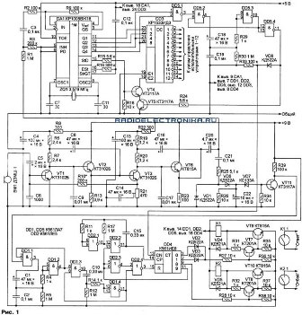
Picture 6. Phone load control device diagram (click on the picture to enlarge)
The circuit is hardware-based, i.e. It does not contain microcontrollers that require software; all the logic of work is achieved due to the circuit itself.
The phone’s call is received by the microphone, amplified to the desired level by an amplifier, as a result of which a relay is activated, the contacts of which are connected to the “Answer” button (pick up the handset). After this relay is activated, a time delay of about 7 seconds is started. If you have time to press the necessary keys, then the DTMF signal will be sent to the DA1 decoder, the output signals of which can be connected via the DD3 decoder via a relay to disconnect up to 12 loads.
After 7 seconds, the “Hang up” relay will work (its contacts are connected to the “hang up” button), for further control you will need another call. Thus, it turns out that the phone, just the whole will be wrapped with wires: wires from the relay to the buttons and even the output of the DTMF signal from the headset jack.
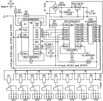
A simpler scheme, referring to the number of parts, is shown in the figure. 7.
Picture 7. Phone load control device diagram (click on the picture to enlarge)
This is where the phone with auto-pickup is used when the headset is connected, so you do not need to solder to the buttons, you just need to connect the headset jack. This circuit provides control of 8 loads, control commands are shown in the circuit description.
But these schemes are not at all the ones that were called the most complex and serious at the beginning of the article. There are those who use the built-in GSM SIM300D module instead of the old cell phone. Its price is 4200 rubles., True, it has already been discontinued. It is in this module that the SIM card is inserted.
For more information on how to independently assemble and program a remote control device in authoring, read here:
A step-by-step instruction on how to independently assemble and configure a load control device on a mobile phone - https://env.electricianexp.com/Electrik_da.zip
Boris Aladyshkin
See also at bgv.electricianexp.com
:

