Categories: Featured Articles » Practical Electronics
Number of views: 162,237
Comments on the article: 4
How to make a do-it-yourself time relay
 What is a time relay? Action algorithm time relay simple enough, but sometimes it can cause admiration. If we recall the old washing machines, which were affectionately called the "bucket with a motor", then the action of the timer was very clear: they turned the knob a few ticks, something started to tick inside, and the engine started.
As soon as the handle pointer reached zero scale division, the wash ended. Later, cars with two timers appeared - washing and spinning. In such machines, the time relays were made in the form of a metal cylinder, in which the clock mechanism was hidden, and outside there were only electrical contacts and a control knob.
Modern washing machines - automatic machines (with electronic control) also have a time relay, and it became impossible to make it out as a separate element or part on the control board. All time delays are obtained programmatically using the control microcontroller. If you look closely at the cycle of the automatic washing machine, the number of time delays simply can not be counted. If all these time delays were performed in the form of a clock mechanism of the aforementioned, then there would simply not be enough space in the body of the washing machine.
Time relay they are used not only in washing machines, for example, in microwave ovens, with the help of time delays not only the operating time is regulated, but also the heating power. This is done as follows: the RF voltage turns on for 5 seconds and turns off for 5. The average heating power in this case is 50%. To get 30% power, turning on the RF for 3 seconds is enough. Accordingly, in the off state, the high-frequency lamp is located for 7 seconds. Of course, these numbers can be different, for example, 50 and 50 or 30 and 70, just here the ratio of the on-off time of the HF is shown.
Mention of old washing machines is given for a reason. It is here, in this example, you can see, even feel with your hands, how the time relay works.
Turning the crank clockwise is nothing more than a shutter speed. The actuator (electric motor) is immediately turned on. The shutter speed, in this case in minutes, determines the angle of rotation of the handle. Thus, two actions are performed at once: loading the exposure time and actually starting the time delay itself. After the set time has passed, the actuator is switched off. All time relays or timers work even approximately, even those that are hidden inside microcontrollers (MK).
From clockwork to electronics
How to get a time delay using MK
The speed of modern MK is very high, up to several tens of mips (millions of operations per second). It seems that not so long ago there was a struggle for 1 mips on personal computers. Now even obsolete MKs, for example, the 8051 family, easily fulfill this 1 mips. Thus, it will take exactly one second to complete 1,000,000 operations.
Here, a seemingly ready-made solution, how to get a time delay. Just perform the same operation a million times. This can be done quite simply if this operation is looped in the program. But the trouble is that in addition to this operation, MK for a second can not do anything else. Here you have the achievement of engineering, here you have mips! And if you need a shutter speed of several tens of seconds or minutes?
Timer - a device for counting time
To prevent such an embarrassment, the processor did not just warm itself up, executing an unnecessary command that would not do anything useful, timers were built into the MK, as a rule, several of them.If you do not go into details, then the timer is a binary counter that counts the pulses generated by a special circuit inside the MK.
For example, in the MK family 8051, a counting pulse is generated when each command is executed, i.e. the timer simply counts the number of machine instructions executed. Meanwhile, the central processing unit (CPU) is quietly engaged in the execution of the main program.
Suppose that the timer starts counting (there is a counter start command for this) from zero. Each pulse increases the contents of the counter by one and, ultimately, reaches the maximum value. After that, the contents of the counter are reset. This moment is called “counter overflow”. This is precisely the end of the time delay (remember the washing machine).
Suppose that the timer is 8-bit, then it can be used to calculate a value in the range 0 ... 255, or the counter will overflow every 256 pulses. To make the shutter speed shorter, it is enough to start the count not from scratch, but from a different value. To get it, it is enough to first load this value into the counter, and then start the counter (once again, remember the washing machine). This preloaded number is the angle of rotation of the time relay.
Such a timer with a frequency of operations of 1 mips will allow you to get a shutter speed of a maximum of 255 microseconds, but you need a few seconds or even minutes, what should you do?
It turns out that everything is quite simple. Each timer overflow is an event that causes the main program to be interrupted. As a result, the CPU switches to the corresponding subprogram, which of such tiny excerpts can add any, at least up to several hours and even days.
The interrupt service routine is usually short, no more than a few dozen commands, after which again there is a return to the main program, which continues to run from the same place. Try this excerpt by a simple repetition of the commands about which it was said above! Although, in some cases, you have to do just that.
To do this, there is a NOP command in the processor command systems, which just does nothing, it only takes machine time. It can be used to reserve memory, and when creating time delays, only very short ones, on the order of a few microseconds.
Yes, the reader will say how he suffered! From washing machines directly to microcontrollers. And what was between these extreme points?
What are time relays?
As already mentioned, The main task of the time relay is to obtain a delay between the input signal and the output signal. This delay can be generated in several ways. The time relays were mechanical (already described at the beginning of the article), electromechanical (also based on a clockwork, only the spring is wound by an electromagnet), as well as with various damping devices. An example of such a relay is the pneumatic time switch shown in Figure 1.
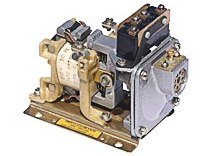
Picture 1. Pneumatic time relay.
The relay consists of an electromagnetic drive and a pneumatic attachment. The relay coil is available at operating voltages of 12 ... 660V AC (16 total ratings) with a frequency of 50 ... 60Hz. Depending on the version of the relay, the shutter speed can start either when it is triggered or when the electromagnetic drive is released.
The time is set by a screw regulating the cross section of the hole for air to exit the chamber. The described time relays differ in not very stable parameters, therefore, wherever possible, electronic time relays are always used. At present, such relays, both mechanical and pneumatic, can perhaps be found only in ancient equipment, which has not yet been replaced with modern equipment, and even in a museum.
Electronic time relays
Perhaps one of the most common was the VL-60 ... 64 relay series and some others, for example, VL-100 ... 140 relays.All these timers were built on a specialized chip KR512PS10. The appearance of the overhead line relay is shown in Figure 2.
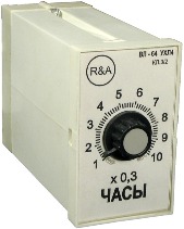
Figure 2. Time relay series VL.
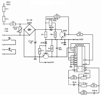
The circuit of the VL - 64 time relay is shown in Figure 3.
Figure 3 Scheme of the timer VL - 64
When a voltage is supplied to the input through the rectifier bridge VD1 ... VD4, the voltage through the stabilizer on the KT315A transistor is supplied to the DD1 chip, the internal generator of which begins to generate pulses. The frequency of the pulses is regulated by a variable resistor PPB-3B (it is it that is displayed on the front panel of the relay), connected in series with a 5100 pF timing capacitor, which has a tolerance of 1% and a very small TKE.
The received pulses are counted by a counter with a variable division coefficient, which is set by switching the terminals of the microcircuit M01 ... M05. In the VL series relay, this switching was performed at the factory. The maximum division ratio of the entire counter reaches 235,929,600. According to the documentation for the microcircuit, at a frequency of the master oscillator 1 Hz, the shutter speed can reach more than 9 months! According to the developers, this is quite enough for any application.
Pin 10 of the END chip is the end of the shutter speed, connected to input 3 - ST start - stop. As soon as a high level voltage appears at the END output, the pulse counting stops, and a high level voltage appears on the 9th output of Q1, which will open the KT605 transistor and the relay connected to the KT605 collector will trip.
Modern time relays
As a rule, are made on MK. It is easier to program a ready-made proprietary microcircuit, add a few buttons, a digital indicator, than invent something new, and then also engage in fine-tuning the time. Such a relay is shown in Figure 4.
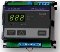
Figure 4 Microcontroller time relay
Why do a do-it-yourself time relay?
And although there is such a huge number of time switches, almost for every taste, sometimes at home you have to do something of your own, often very simple. But such designs often justify themselves completely and completely. Here is some of them.
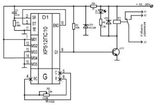
As soon as we just examined the operation of the KR512PS10 microcircuit as part of the overhead line relay, we will have to start considering amateur circuits from it. Figure 5 shows the timer circuit.
Figure 5. Timer on the KR524PS10 microcircuit.
The microcircuit is powered from the parametric stabilizer R4, VD1 with a stabilization voltage of about 5 V. At the time of power-up, the R1C1 circuit generates a microcircuit reset pulse. This starts the internal generator, the frequency of which is set by the R2C2 chain and the internal counter of the microcircuit starts counting pulses.
The number of these pulses (counter division ratio) is set by switching the terminals of the microcircuit M01 ... M05. With the position indicated in the diagram, this coefficient will be 78643200. This number of pulses makes up the full period of the signal at the output END (pin 10). Pin 10 is connected to pin 3 ST (start / stop).
As soon as the END output is set to a high level (half a period has been counted), the counter stops. At the same time, the output Q1 (pin 9) also sets a high level, which opens the transistor VT1. Through an open transistor, relay K1 is turned on, which controls the load with its contacts.
In order to start the time delay, it is enough to briefly turn off and on again the relay. The timing diagram of the END and Q1 signals is shown in Figure 6.
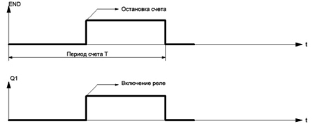
Figure 6. Timing diagram of END and Q1 signals.
With the values of the R2C2 timing chain indicated on the diagram, the generator frequency is about 1000 Hz. Therefore, the time delay for the indicated connection of the terminals M01 ... M05 will be about ten hours.
To fine tune this shutter speed, the following should be done. Connect the terminals M01 ... M05 to the position "Seconds_10", as shown in the table in the figure 7.
Figure 7. Timer setting table (click on the picture to enlarge).
With this connection, rotate the variable resistor R2 to adjust the shutter speed for 10 seconds. by stopwatch. Then connect the terminals M01 ... M05, as shown in the diagram.
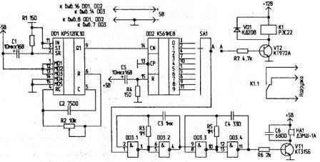
Another diagram on KR512PS10 is shown in Figure 8.
Figure 8 Chip time relay KR512PS10
Another timer on the KR512PS10 chip.
To begin with, let's pay attention to the KR512PS10, more precisely, to the END signals, which are not shown at all, and the ST signal, which is simply connected to a common wire, which corresponds to a logic zero level.
With this switching on, the counter will not stop, as shown in Figure 6. The END and Q1 signals will cyclically, without stopping, continue. The shape of these signals will be a classic meander. Thus, it turned out just a generator of rectangular pulses, the frequency of which can be controlled by a variable resistor R2, and the counter division factor can be set according to the table shown in Figure 7.
Continuous pulses from the output Q1 go to the counting input of the decimal counter - decoder DD2 K561IE8. The R4C5 chain, when turned on, resets the counter to zero. As a result, a high level appears at the output of the decoder “0” (pin 3). At outputs 1 ... 9 low levels. With the arrival of the first counting pulse, a high level moves to output "1", the second pulse sets a high level at output "2" and so on, up to output "9". Then the counter overflows and the counting cycle begins anew.
The resulting control signal through the switch SA1 can be fed to the sound generator on the elements DD3.1 ... 4, or to the relay amplifier VT2. The amount of time delay depends on the position of switch SA1. With the terminal connections M01 ... M05 indicated on the diagram and the parameters of the R2C2 timing chain, it is possible to obtain time delays ranging from 30 seconds to 9 hours.
Boris Aladyshkin
See also at bgv.electricianexp.com
:

