Categories: Practical Electronics, Electrician Secrets
Number of views: 121618
Comments on the article: 3
How to connect the load to the control unit on microcircuits
 An article on various ways of connecting a load to a microcontroller control unit using relays and thyristors.
All modern equipment, both industrial and domestic, is powered by electricity. At the same time, its entire electrical circuit can be divided into two large parts: control devices (controllers from the English word CONTROL - to control) and actuators.
About twenty years ago, control units were implemented on microcircuits of small and medium degree of integration. These were the series of chips K155, K561, K133, K176 and the like. They're called logic digital circuits, since they perform logical operations on signals, and the signals themselves are digital (discrete).
Just like regular contacts: “closed - open”. Only in this case are these states called, respectively, “logical unit” and “logical zero”. The voltage of the logic unit at the output of the microcircuit is in the range from half the supply voltage to its full value, and the voltage of the logical zero for such microcircuits is usually 0 ... 0.4V.
The operation algorithm of such control units was carried out due to the corresponding connection of microcircuits, and their number was quite large.
Currently, all control units are developed based on microcontrollers of various types. In this case, the operation algorithm is laid down not by a circuit connection of individual elements, but by a program “stitched” in the microcontroller.
In this regard, instead of several tens, or even hundreds of microcircuits, the control unit contains a microcontroller and a number of microcircuits for interaction with the "outside world". But, despite such an improvement, the signals of the microcontroller control unit are still the same digital as those of old microcircuits.
It is clear that the power of such signals is not enough to turn on a powerful lamp, engine, and just a relay. In this article we will consider in what ways can powerful loads be connected to microcircuits.
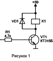
The most simple ways is to turn on the load through the relay. In Figure 1, the relay is switched on using the transistor VT1, for this purpose, a logical unit is supplied to its base through the resistor R1 from the microcircuit, the transistor opens and turns on the relay, which, with its contacts (not shown), turns on the load.
The cascade shown in figure 2 works differently: in order to turn on the relay, a logic 0 must appear at the output of the microcircuit, which will close the VT3 transistor. In this case, the transistor VT4 will open and turn on the relay. Using the SB3 button you can turn on the relay manually.
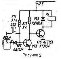
In both figures, you can see that parallel to the relay windings, diodes are connected, and with respect to the supply voltage in the opposite (non-conducting) direction. Their purpose is to suppress the self-induction EMF (it can be ten or more times the supply voltage) when the relay is turned off and protect the circuit elements.
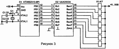
If in the circuit there is not one, two relays, but much more, then to connect them specialized chip ULN2003Aallowing connection of up to seven relays. Such a switching circuit is shown in Figure 3, and in Figure 4 the appearance of a modern small-sized relay.
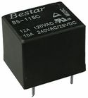
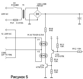
Figure 5 shows load connection diagram using TO125-12.5-6 optocoupler thyristors (instead of which without changing anything in the circuit, you can connect a relay). In this circuit, you should pay attention to the transistor switch made on two transistors VT3, VT4. This complication is caused by the fact that some microcontrollers, for example, AT89C51, AT89C2051, during reset, turn on for several milliseconds and hold logic 1 on all pins.If the load is connected according to the scheme shown in Figure 1, then the load will be triggered immediately when the power is turned on, which can be very undesirable.
In order to turn on the load (in this case, the LEDs of the optocoupler thyristors V1, V2), a logical 0 should be supplied to the base of the transistor VT3 through the resistor R12, which will open VT3 and VT4. The latter will light up the opto-thyristor LEDs that open and turn on the network load. Optocoupler thyristors provide galvanic isolation from the network of the control circuit itself, which increases the electrical safety and reliability of the circuit.
A few words about thyristors. Without going into technical details and current-voltage characteristics, we can say that thyristor - This is a simple diode, they even have similar designations. But the thyristor also has a control electrode. If a positive impulse with respect to the cathode is applied to it, even short-term, then the thyristor will open.
In the open state, the thyristor will remain until a current flows through it in the forward direction. This current must be at least some value called the holding current. Otherwise, the thyristor simply will not turn on. You can turn off the thyristor only by breaking the circuit or by applying a voltage of reverse polarity. Therefore, in order to miss both half-waves of alternating voltage, counter-parallel connection of two thyristors is used (see Fig. 5).
In order not to make such an inclusion are issued triacs or in bourgeois triacs. In them already in one case two thyristors are made, connected in opposite - in parallel. The control electrode is common.
Figure 6 shows the appearance and pinout of the thyristors, and Figure 7 shows the same for triacs.
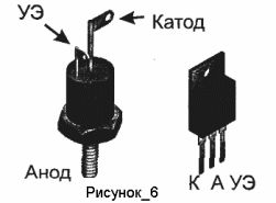
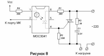
Figure 8 shows scheme for connecting a triac to a microcontroller (microcircuit output) using a special low-power optotriac type MOC3041.
This driver inside contains an LED connected to pins 1 and 2 (the figure shows a view of the microcircuit from above) and the optotriac itself, which, when illuminated by an LED, opens (pins 6 and 4) and, through resistor R1, connects the control electrode to the anode , due to which a powerful triac opens.
The resistor R2 is designed so that the triac does not open in the absence of a control signal at the time of power-up, and the chain C1, R3 is designed to suppress interference at the time of switching. True, the MOC3041 does not create any special interference, since it has a CROSS ZERO circuit (voltage transition through 0), and switching on occurs at the moment when the mains voltage only passed through 0.
All the considered circuits are galvanically isolated from the mains, which ensures reliable operation and electrical safety with significant switched power.
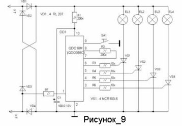
If the power is negligible and the galvanic isolation of the controller from the network is not required, then it is possible to connect the thyristors directly to the microcontroller. A similar scheme is shown in Figure 9.
This is a circuit Christmas garland producedOf course in China. Thyristor control electrodes MCR 100-6 through resistors connected directly to the microcontroller (located on the board under a drop of black compound). The power of the control signals is so small that the current consumption for all four at once, less than 1 milliampere. In this case, the reverse voltage is up to 800V and the current is up to 0.8A. Overall dimensions are the same as for KT209 transistors.
Of course, in one short article it is impossible to describe all the schemes at once, but, it seems, they managed to tell the basic principles of their work. There are no special difficulties here, the schemes are all tested in practice and, as a rule, do not bring grief during repairs or self-production.
EBook -Beginner's Guide to AVR Microcontrollers
Boris Aladyshkin
See also at bgv.electricianexp.com
:

