About electrical protection devices for dummies: fuses
 Fuses are designed to protect electrical networks from overloads and short circuits. They are very cheap and elementary simple in design. These devices are rightfully considered pioneers of circuit protection.
The fuse consists of two main parts: a body made of electrical insulation material (glass, ceramics) and a fuse (wire, metal strips). The outputs of the fuse-link are connected to the terminals, with the help of which the fuse is connected in series with the protected consumer or the circuit section. To do this, use special terminal holders. They must ensure reliable contact of the fuse - otherwise heating is possible in this place.
The fusible insert is selected so that it melts before the temperature of the line wires reaches a dangerous level or an overloaded consumer fails.
By design features distinguish between plate, cartridge, tube and plug fuses. The current strength for which the fuse is designed is indicated on its body. The maximum permissible voltage at which a fuse can be used is also specified.
The main characteristic of the fusible insert is the dependence of the time of its burnout on current. This dependency is the following graph ...
How to easily control a powerful AC load
 Sometimes you need a weak signal from the microcontroller to turn on a powerful load, such as a lamp in the room. This problem is especially relevant for smart home developers. The first thing that comes to mind is a relay. But do not rush, there is a better way :)
In fact, the relay is a continuous hemorrhage. Firstly, they are expensive, and secondly, to power the relay coil, an amplifying transistor is needed, since the weak leg of the microcontroller is not capable of such a feat. Well, and thirdly, any relay is a very bulky design, especially if it is a power relay, designed for high current.
If we are talking about alternating current, then it is better to use triacs or thyristors. What it is? And now I’ll tell you.
If on the fingers, then the thyristor is similar to a diode, even the designation is similar. Passes current in one direction and does not let in the other. But he has one feature that distinguishes it from the diode radically - the control input.
If the opening current is not applied to the control input, the thyristor will not pass current even in the forward direction. But it is worth giving at least a brief impulse, as it immediately opens and remains open as long as there is direct voltage. If the voltage is removed or polarity reversed, the thyristor will close ...
Why do I need an oscilloscope?
 Sooner or later, any novice electronics engineer, if he does not give up his experiments, will grow to circuits where you need to monitor not just currents and voltages, but the operation of the circuit in dynamics. This is especially often needed in various generators and pulse devices. There is nothing to do without an oscilloscope!
Scary device, huh? A bunch of pens, some buttons, and even the screen and nifiga is not clear what is here and why. Nothing, we’ll fix it now. Now I’ll tell you how to use the oscilloscope.
In fact, everything is simple here - the oscilloscope, roughly speaking, is just ... voltmeter! Only cunning, able to show a change in the shape of the measured voltage ...
About grounding and grounding for "dummies"
 My bitter experience as an electrician allows me to say: If you have the "grounding" done as it should - that is, the shield has a connection point for the "grounding" conductors, and all the plugs and sockets have "grounding" contacts - I envy you, and there’s nothing for you worry.
Grounding Rules
What is the problem, why can not you connect the ground wire to the heating or water pipes?
Actually, in urban conditions, stray currents and other interfering factors are so great that anything can appear on the heating battery. However, the main problem is that the trip current of the circuit breakers is quite large. Accordingly, one of the options for a possible accident is a breakdown of a phase to a case with a leakage current just somewhere on the machine operation boundary, that is, at best 16 amperes. Total, we divide 220v by 16A - we get 15 ohms. Just some thirty meters of pipes, and get 15 ohms. And the current flowed somewhere, in the direction of not sawn wood. But that is no longer important. The important thing is that in the next apartment (up to which 3 meters, and not 30, the voltage on the tap is almost the same 220.), but on, say, the sewer pipe - a real zero, or so.
And now the question is - what will happen to the neighbor if he, sitting in the bathroom (connected to the sewer by opening the cork), touches the tap? Guessed?
The prize is prison. According to the article on violation of electrical safety rules that caused the victim.
Do not forget that you can not do an imitation of the "grounding" circuit, connecting the "zero working" and "zero protective" conductors in the Euro socket, as some "craftsmen" sometimes practice. Such a replacement is extremely dangerous. Cases of burning off the “working zero” in the shield are not uncommon. Thereafter ...
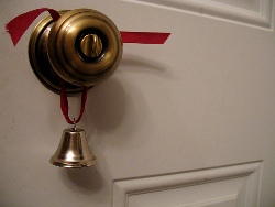 Some models of bells or bells have batteries inside the case, others have built-in transformers that reduce the mains voltage of 220 V (or 230 V) to small values necessary for this type of electrical appliance. In many models, both power methods can be used. Most of them use two or four batteries with a voltage of 1.5 V, and some use one battery with a voltage of 4.5 V.
Commercially available transformers for doorbell circuitry typically have three pairs of 3, 5, and 8 V pins (contacts) that can be used in various types of bells. As a rule, 3 and 5 V are used in calls and buzzer, and 8 V is suitable for many bell variants.
However, some bell models require a higher voltage, and they need transformers with 4, 8, and 12 V outputs. The bell transformer must be designed so that the mains voltage cannot reach the low voltage windings.
Batteries, buttons and bells are connected by a two-core insulated “bell wire”. This thin wire is usually laid on the surface and fastened with small piercing brackets. The bell wire also connects the bell and button to a transformer.
Connect the double-insulated bell transformer to the junction box or ceiling socket of the lighting circuit with a two-wire rigid wire ...
Entertaining experiments. The new design of the simplest electric motor
 We will assemble a more stable, elegant and compact version of the electric motor.
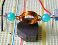
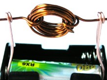
We use the mounting plate as the base, which will provide us with a stable base and internal electrical connections, and the AAA battery as the frame for the coil.
In the form of an experiment, we wind only 5 turns of wire to make sure whether our electric motor will work with such a coil. For convenience, add a current switch.
Here is the motor in assembled form, and here - and in working condition. As you can see, everything works ...
How to install a power outlet. Detailed photo instructions for installing outlets
 Before installing the outlet, you must turn off the circuit breaker in the electrical panel in the apartment or on the stairwell. In this case, you must make sure that it has worked and there is no voltage in the outlet. This can be checked using a screwdriver indicator or a multimeter.
To install the sockets, we need the following tools: level, knife, pencil, screwdriver, pliers, wire cutters.
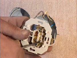
Consider installing a double socket, where in one part it will be electric, and in the other a telephone jack. For ease of installation, the wires should protrude from the box by 50 - 80 millimeters. For strict horizontal installation of the outlet, using the level, mark on the sides of the place of internal mounting of the outlet. Having pulled out the wires, carefully clean their ends from the factory insulation. The bare ends of the wires, it is advisable to do no longer than 10 millimeters.
Modern wiring has three wires and is called a three-wire, one of the three wires is grounding, the other phase and the third neutral wire. The indoor unit of the outlet is equipped with three terminals, to which these three cores are connected.
After checking that the wires are not intertwined under the outlet, we begin the installation, according to our marking ...
How to make a simple electric motor in ten minutes
 It is always interesting to observe changing phenomena, especially if you yourself are involved in the creation of these phenomena. Now we will assemble the simplest (but really working) electric motor, consisting of a power source, a magnet and a small coil of wire, which we ourselves will do.
There is a secret that will make this set of items become an electric motor; a secret that is both smart and amazingly simple. Here is what we need:
-
1.5V battery or battery.
-
Holder with contacts for the battery.
-
Magnet.
-
1 meter of wire with enamel insulation (diameter 0.8-1 mm).
-
0.3 meters of bare wire (diameter 0.8-1 mm).
We will start by winding the coil, the part of the electric motor that will rotate. We will start by winding the coil, that part of the electric motor that will rotate. To make the coil sufficiently smooth and round, wrap it on a suitable cylindrical frame, for example, on a AA size battery ....