Logic chips. Part 7. Triggers. RS - trigger
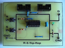 Electronic devices with two stable output states are called triggers. A trigger is translated into one of the stable states by input pulses.
A similar formulation is given, as a rule, in all technical literature. For the one who came across it for the first time, it may not be entirely clear. What are these two states, and why are they called stable?
The easiest way to explain this is with a simple and accessible example. A fairly close and understandable analogue can be an ordinary light bulb with a switch. There are two states here: on - off. For a trigger, these states are high, low. It is also sometimes said, on - off, installed - reset.
In order to light or turn off the light bulb, just touch the switch. In order for the bulb to continue to burn, it is not necessary to hold the switch with your finger: the bulb will burn indefinitely ...
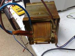 If physics was well taught at your school, then you probably will remember the experience that clearly explained the phenomenon of electromagnetic induction.
Outwardly, it looked something like this: the teacher came to the classroom, the attendants brought in some appliances and placed them on the table. After explaining the theoretical material, a demonstration of experiments began, which clearly illustrates the story.
To demonstrate the phenomenon of electromagnetic induction, a very large inductor, a powerful direct magnet, connecting wires and a device called a galvanometer were required.
The galvanometer in appearance was a flat box a little larger than a standard A4 sheet, and behind the front wall, which was closed by glass, a scale with a zero in the middle was placed. Behind the same glass one could see a thick black arrow ...
 In the second part of the article, we talked about the conditional graphic designations of logical elements and about the functions performed by these elements.
To explain the principle of operation, contact circuits performing the logical functions of AND, OR, NOT and AND-NOT were given. Now you can begin to practical acquaintance with the K155 series microcircuits.
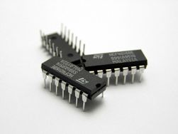
The basic element of the 155th series is the K155LA3 chip. It is a plastic case with 14 leads, on the upper side of which is marked and a key that indicates the first output of the chip.
The key is a small round mark. If you look at the microcircuit from above (from the side of the case), then the conclusions should be counted counterclockwise, and if from below, then clockwise ...
What is protective grounding and how does it work
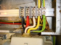 Protective grounding, purpose and principle of action.
Currently, there are several different power supply systems for consumers with voltages up to 1000 V, however, in Russia, the main one in this case is a system with dead-grounded neutral. It is such a system that is used in each of our homes.
With the apparent complexity of the name, everything is extremely simple. In such a system, the neutral point of the transformer at the substation is directly connected to the ground. The main measure of protection against accidental undervoltage in this case is protective grounding, that is, a special connection of any metal part of the household appliance with the neutral of the transformer ...
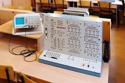 Logical elements operate as independent elements in the form of microcircuits of a small degree of integration, and they are included as components in microcircuits of a higher degree of integration. Such elements can be counted more than a dozen.
But first, we’ll only talk about four of them - these are the elements AND, OR, NOT, AND-NOT.The main elements are the first three, and the AND-NOT element is already a combination of the AND AND NOT elements. These elements can be called "bricks" of digital technology. First you need to consider what is the logic of their action?
Recall the first part of the article on digital circuits. It was said that the voltage at the input (output) of the microcircuit within 0 ... 0.4 V is a logic zero level, or a low voltage level. If the voltage is within 2.4 ... 5.0 V, then this is the level of a logical unit or a high level voltage ...
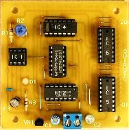 Introductory article about logic chips. Describes number systems and the representation of a binary number using electrical signals.
The modern digital integrated circuit is a miniature electronic unit, the housing of which contains active and passive elements connected in a certain pattern. These are transistors, diodes, resistors and capacitors.
The number of elements in modern microcircuits can reach several hundred thousand and even millions of elements. It is enough to recall microprocessors, microcontrollers, memory chips.
To simply list all modern microcircuits, you will need not one article, but a whole rather thick book. In this article, we will consider microcircuits of small and medium degree of integration, mostly simple logic elements ...
Boolean algebra. Part 3. Contact schemes
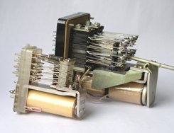 The article describes the basic principles of designing relay circuits in accordance with a given algorithm of their operation.
The two previous articles described the basics of Boolean algebra and the algebra of relay circuits. On this basis, structural formulas were developed, and already typical contact circuits were developed on them.
Drawing up a structural formula according to a ready-made scheme is a simple matter. It is much more difficult to present the electrical circuit of the future machine according to the ready-made structural formula. It needs some training!
Figure 1 shows the most common contact circuit options and their equivalents. They will help in the preparation of electrical circuits of machines, as well as analyze ready-made structures, for example, in the process of repairing them.
How can you use the options for contact circuits discussed above? ...
Boolean algebra. Part 2. Basic laws and functions
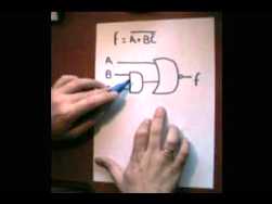 Continuation of the story about Boolean algebra, conventions, rules, operations. Transition to the basics of contact circuits.
The first article talked about George Bull as the creator of the algebra of logic. The second article will describe the basic operations of Boolean algebra, and methods for simplifying Boolean expressions. So, Boolean algebra uses statements as arguments, and not their meaning, but the truth or falsity of the statement.
If the statement is true, then it is written like this: A = 1, if it is false, then A = 0 (it is not true that potato is a fruit). (See the end of article No. 1). For any statement, A is either true (A = 1) or false (A = 0). There cannot be a middle here ...
