Categories: Featured Articles » Practical Electronics
Number of views: 32799
Comments on the article: 2
Electronic amplifiers
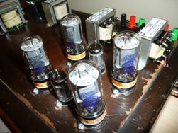 The term amplifier is very ambiguous. It can be a hydraulic booster, well known to motorists, a magnetic amplifier, which was once used in automation systems. Electromechanical and relay amplifiers are also known.
The principle of operation of all amplifiers is the same: under the influence of a weak control signal, a powerful output signal appears at the output of the amplifier. Naturally, to obtain an output signal of high power requires an external energy source.
For example, controlling a relay coil requires a fraction of a watt of power, while contacts can switch a load of several kilowatts. As they say, there is a gain in power. But in this article only electronic amplifiers will be briefly reviewed.
Electronic amplifiers
They are the most common node of various devices and devices. Depending on the function performed, on the nature of the input signal, amplifiers are divided into several types. In one case, for example, thermocouple signaland in another, music, speech or a signal from a television antenna operating in the decimeter wavelength range.
But all electronic amplifiers are united by the fact that they use the phenomenon of electrical conductivity in various environments. First of all, these are vacuum (electron tubes) and semiconductors (transistors and chips).
Most electronic amplifiers are currently made on semiconductors, lamp designs are used by lovers of very high-quality sound, music lovers, and even where it is impossible to do without lamps.
Amplifiers can be structurally either a separate device or an integral part of any device, for example, a measuring one.
Amplifiers of a direct current (UPT)
These amplifiers operate in the frequency range from zero to some upper frequency. In other words, they are able to amplify a constant voltage. In this case, of course, the variable component of the signal is also amplified. A diagram, if not all, of some part of the UPT is shown in Figure 1.
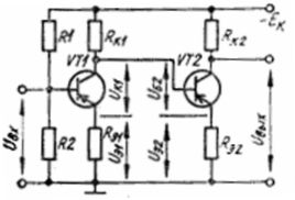
Figure 1. DC amplifier circuit
In order to be able to strengthen the "constant", the connection between the cascades is carried out using resistors, diodes, zener diodes, or even directly. It is this option that is shown in Figure 1. The most widely used UPTs are found in automation systemsconverters of non-electric quantities, in measuring instruments, in signal amplifiers of different sensors.
UPT are also the basis for the creation of operational amplifiers (op amps), which are widely used in various devices. Actually, all UPTs are currently built on the basis of OS, the advantages of which are widely known and are not subject to any doubt.
Figure 2 shows a circuit diagram of an operational amplifier based on an operational amplifier. As you can see, it is much simpler than the previous one, although its parameters are much better.
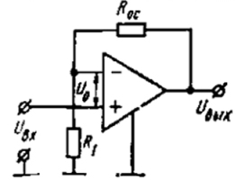
Figure 2. DT based on op-amp
AC Amplifiers
AC amplifiers differ from CTD in that they only amplify the variable component of the input signal. As an example, Figure 3 shows a microphone amplifier for a dynamic microphone such as MD-52 or the like, which was equipped with domestic tape recorders.
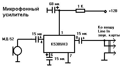
Figure 3. Microphone Amplifier
Separating capacitors are installed at the input and output of the amplifier made on the microcircuit, which allows passing through the amplifier only the variable component of the signal.
Such a circuit is also called a microphone amplifier. Being connected to the computer’s sound card, the mentioned microphone allows you to get great sound, much better than using a Chinese computer microphone.
The amplifier works fine even from + 5V, so you can power it from the USB connector, or remove 12 volts from the computer. The device does not require adjustment, it starts working immediately. A small number of parts allows you to assemble this circuit with a mounted installation using the findings of the parts. In doing so, strive to keep the compounds as short as possible. This will save from interference and interference.
High frequency amplifiers
They are mainly used in radios and televisions. Their purpose is to somewhat enhance the input signal, for example, from an antenna. Next, the superheterodyne conversion occurs, and further main amplification occurs at an intermediate frequency. The specifics of such amplifiers is the use of RF transistors, as well as the installation features of the device. A similar installation can be seen if you open the radio frequency unit of any modern TV.
Band Amplifiers
Band amplifiers are designed to amplify signals in a narrow frequency range. An example is the intermediate frequency amplifiers (IF). The frequency band in such amplifiers is provided by oscillatory circuits and filters of concentrated selection (FSS) or piezoceramic filters (PCF). Indeed, amplifying a signal in a narrow frequency band is much simpler than creating a very broadband amplifier.
In addition to the amplifiers already mentioned, there are a very large number of varieties, here are some more of them.
Preamplifiers
Their purpose is to amplify the signal from a weak source to a level acceptable for further cascades. For example, raise the level of the set-top box to the input level of the terminal audio amplifier. The preamplifier may also include tone and volume controls.
To play back the recordings from vinyl discs, special preliminary corrector amplifiers are used that form the frequency response for working with the pickup head. When music was recorded and listened to on tape recorders, recording and playback amplifiers were in use. The purpose of such amplifiers was to form the required frequency response of the recording - playback channel.
Amplifiers
Most often used in measuring instruments, automation, controllers for industrial equipment. These amplifiers are also called instrumental amplifiers. They have a very low intrinsic noise, a very large gain (with a broken OS circuit) and a very high common mode rejection ratio. Such very high characteristics are achieved by using a particular compound of several op-amps. Here is how many “very” measuring amplifiers have. Figure 4 shows a classic instrumentation amplifier circuit.
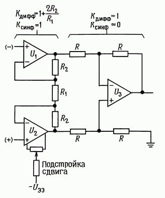
Figure 4Instrumentation amplifier circuit
Along with this circuit, circuits on one op amp or two are also widely used. There are more complex designs. Recently, measuring amplifiers have been produced in an integral version - everything that is shown in Figure 4 fits in one housing, while the number of tuning elements is minimal, usually one external resistor. In Figure 4, this is R1, and in Figure 5, the resistor is RG (GAIN).
The internal structure of the integrated measuring amplifier type AD623, of course, a simplified circuit is shown in Figure 5. A distinctive feature of this amplifier is its low price and the ability to work with unipolar power.
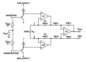
Figure 5. Schemeintegrated measuring amplifier type AD623
You can find out more about electronic amplifiers here.
Boris Aladyshkin
See also at bgv.electricianexp.com
:
