Categories: Featured Articles » Practical Electronics
Number of views: 79276
Comments on the article: 4
Logic chips. Part 10. How to get rid of the bounce of contacts
 Using a trigger as a switch
In the previous parts of the article, triggers like D and JK were described. It will be appropriate here to recall that these triggers can work in counting mode. This means that when the next pulse arrives at the clock input (for both triggers this is input C), the state of the trigger changes to the opposite.
This logic of operation is very similar to the usual electric button, as in a table lamp: pressed - on, pressed again - off. In devices based on digital microcircuits, the role of such a button is most often performed by triggers operating in counting mode. High-level pulses are supplied to the counting input, and the trigger output signals are used to control the executive circuits.
It would seem very simple. If you simply connect a button to input C that connects this input to a common wire when pressed, then with each press the trigger state will change, as expected, to the opposite. To make sure that this is not so, it is enough to assemble this circuit and push the button: the trigger will not be installed in the right position every time, but more often after several button presses.
The trigger condition is best monitored using an LED indicator, which has been repeatedly described in the previous parts of the article, or simply using a voltmeter. Why does this happen, why does the trigger work so unstably, what is the reason?
What is contact bounce
It turns out that the bounce of contacts is to blame for everything. What is it? Any contacts, even the best, even reed switchesIt turns out that they do not close immediately. Their reliable connection is hindered by a whole series of collisions, which lasts about 1 millisecond or even more. That is, if we pressed the button and hold it pressed for half a second, this does not mean at all that only one impulse of such a duration has formed. Its appearance is preceded by several tens, or maybe even hundreds of impulses.
Coming to the counting input of the trigger, each such pulse switches it to a new state, which fully corresponds to the logic of the trigger in counting mode: all pulses will be counted, and the result will correspond to their number. And the task is to press the button one time to change the trigger state only once.
A similar problem is even more noticeable when the mechanical contact is a speed sensor, for example, in a device for winding transformers, or in a liquid flow meter: each contact operation increases the state of the electronic meter not by one, as expected, but by a random number. The story about the counters will be a little later, but for now, just believe that this is exactly so, and not otherwise.
How to get rid of the bounce of contacts
The way out is shown in Figure 1.
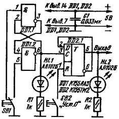
Figure 1. Pulse former on the RS - trigger.
The easiest way is to eliminate contact bounce with the help of the already familiar RS - trigger, which is assembled on a K155LA3 logic chip, more precisely on its elements DD1.1 and DD1.2. Let's agree that direct exit RS - trigger this is pin 3, respectively, the inverse output is pin 6.
When the RS - trigger is assembled from elements of logic circuits, it is necessary to make such an agreement. If the trigger is a finished microcircuit, for example K155TV1, the position of the direct and inverse outputs is specified by its reference data. But, even in this case, if the JK and C inputs are not used, and the microcircuit is used simply as an RS-trigger, the above agreement may be quite appropriate. For example, for ease of mounting the chip on the board.Of course, at the same time the RS - inputs are also swapped.
In the switch position shown in the diagram, on the direct output of the RS-trigger, the level is a logical unit, and on the inverse, of course, a logical zero. The status of the counting trigger DD2.1 so far remains the same as it was when the power was turned on.
If necessary, it can be reset using the SB2 button. To reset the trigger when the power is turned on, a small capacitor is connected between the R - input and the common wire, within 0.05 ... 0.1 μF, and a resistor with a resistance of 1 ... 10 KOhm between the power plus and R - input. Until the capacitor is charged at the R - input, a logical zero voltage is briefly present. This short zero pulse is enough to reset the trigger. If, according to the operating conditions of the device, it is necessary to set the trigger at power-on to a single state, then such an RC-chain is connected to the S-input. We will consider the paragraph about the RC-chain as a lyrical digression, and now we continue about fighting the bounce of contacts.
Pressing the SB1 button will close its right-hand contact pin to the common wire. At the same time, at terminal 5 of the DD1.2 microcircuit, a whole series of bounce pulses will appear. But the performance of microchips of even the slowest series is much higher than the speed of mechanical contacts. And therefore, the very first pulse of RS - the trigger will reset to zero, which corresponds to a high level at the inverse output.
At this moment, a positive voltage drop is formed on it, which, at the C - input, switches the trigger DD2.1 to the opposite state, which can be observed using the LED HL2. Subsequent bounce pulses do not affect the state of the RS-trigger, therefore, the state of the trigger DD2.1 remains unchanged.
When you release the button SB1, the trigger on the elements DD1.1 DD1.2 goes back to a single state. At this moment, a negative voltage drop is formed at the inverted output (pin 6 DD1.2), which does not change the state of trigger DD2.1. In order to return the counting trigger to its original state, the SB1 button will have to be pressed again. With the same success in a similar device will work and JK - trigger.
Such a shaper is a typical circuit and works clearly and without fail. Its only drawback is the use of a flip contact button. Below will be shown similar shapers, working from a button with a single contact.
Measures to eliminate false alarms, anti-jamming
In the diagram, you can see a new part - capacitor C1, installed in the trigger power circuit. What is his purpose? Its main task is to protect against interference, to which not only triggers are sensitive, but also all other microcircuits.
If you touch the mounting elements with a metal object, then they will create impulse noise that can change the state of the triggers as you like. The same interference in the circuit is created when even one trigger is used, especially several. This interference is transmitted through the power buses from one chip to another and can also cause false trigger switching.
To prevent this from happening on the power buses and install blocking capacitors. In practice, such capacitors with a capacity of 0.033 ... 0.068 μF are installed at the rate of one capacitor for every two or three microcircuits. These capacitors are mounted as close as possible to the power terminals of the microcircuits.
Another source of false triggering of microchips can be unused input pins. Spurious interference pulses will be induced primarily on such conclusions. To combat false alarms, unused input terminals should be connected through resistors with a resistance of 1 ... 10 KOhm to the positive bus of the power source. In addition, if the scheme has unused logical elements AND NOT, then their inputs should be connected to a common wire, which is why a logical unit will appear at the output of such elements, and connect unused trigger inputs to them already.
If a toggle switch or button is used as a signal source for a microcircuit, then the situation when the contact is open and a sufficiently long wire remains “hanging in the air” is completely unacceptable. Already such an antenna will receive interference very successfully. Therefore, such conductors should be connected to the positive power bus through a resistor with a resistance of 1 ... 10 KOhm.
Button chatter suppression with one pair of contacts
Using buttons with one pair of contacts is much simpler, so they are used more often than buttons with rocker contacts. Several circuits designed to suppress the chatter of contacts of such buttons are shown in Figure 2.

Figure 2
The operation of these circuits is based on time delays created using RC chains. Figure 2a shows a circuit whose operation delays switching on and off, Figure 2c contains a circuit with a delay only on, and Figure 2d shows a circuit with a delayed shutdown. These circuits are single vibrators, which have already been written about in one part of this article. Figures 2b, 2d, 2e show their time diagrams.
It is easy to see that these formers are made on microcircuits of the K561 series, which refers to CMOS microcircuits, therefore the values of resistors and capacitors are indicated specifically for such microcircuits. These shapers should be used in circuits built on microcircuits of the K561, K564, K176 series and the like.
Boris Aladyshkin
See also at bgv.electricianexp.com
: