Categories: Featured Articles » Practical Electronics
Number of views: 51355
Comments on the article: 0
Logic chips. Part 5 - One Vibrator
 The scheme of a single vibrator and the principle of its operation according to the time diagram.
IN previous article It was told about multivibrators made on a logic chip K155LA3. This story would be incomplete if not to mention one more kind of multivibrator, the so-called single-vibrator.
Single vibrator
A single vibrator is a single pulse generator. The logic of his work is as follows: if a short pulse is applied to the input of a single-shot, then a pulse is generated at its output, the duration of which is given by an RC chain.
After this pulse ends, the single-shot goes into the standby state of the next trigger pulse. Because of this, a single vibrator is often called a standby multivibrator. The simplest single-vibrator circuit is shown in Figure 1. In practice, in addition to this circuit, several dozen varieties of single-vibrator are used.
Figure 1. The simplest single vibrator.
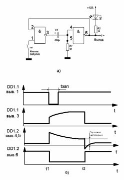
Figure 1a shows a single vibrator circuit, and Figure 1b shows its timing diagrams. The single vibrator contains two logical elements: The first of them is used as a 2N-NOT element, while the second is turned on according to the inverter circuit.
3single-shot is started using the SB1 button, although this is only for educational purposes. Actually, a signal from other microcircuits can be applied to this input. An LED indicator, also shown in the diagram, is also connected to the output to indicate the status. Of course, it is not a part of a single vibrator, so it can be omitted.
Capacitor C1 selected large capacity. This is done so that the pulse has a duration sufficient for indication with a pointer device having a large inertia. The minimum capacitance of the capacitor at which it is still possible to detect a pulse with a dial gauge 50 μF, the resistance of the resistor R1 is in the range 1 ... 1.5 kOhm.
In order to simplify the circuit, it would be possible to do without the SB1 button, closing the output of 1 chip to a common wire. But with such a solution, malfunctions in the operation of the one-shot will sometimes occur due to contact bounce. A detailed discussion of this phenomenon and methods of dealing with it will be discussed a little later in the description of counters and a frequency meter.
After the one-shot is assembled, and the power is applied, we measure the voltage at the inputs and outputs of both elements. At the output 2 of the element DD1.1 and the output 8 of the element DD1.2 there should be a high level, and at the output of the element DD1.1 - low. Therefore, we can say that in standby mode the second element, the output, is in the single state, and the first is in the zero state.
Now connect a voltmeter on the output of the element DD1.2 - the voltmeter will show a high level. Then, observing the arrow of the device, briefly press the button SB1. the arrow quickly deviates to almost zero.
After about 2 seconds, it will also sharply return to its original position. This indicates that the pointer device showed a low level pulse. In this case, the LED will also light up through the output of the DD1.2 element. If you repeat this experiment several times, then the results should be the same.
If one more parallel is connected to the capacitor - with a capacity of 1000 μF, the pulse duration at the output will triple.
If the resistor R1 is replaced by a variable value of about 2 Kom, then by rotating it, it is possible to change the duration of the output pulse to some extent. If you unscrew the resistor so that its resistance becomes less than 100 ohms, then the single-shot simply stops generating pulses.
From the experiments performed, the following conclusions can be drawn: the greater the resistance of the resistor and the capacitance of the capacitor, the longer the pulse generated by a single-shot.In this case, the resistor R1 and capacitor C1 are a timing RC circuit, on which the duration of the generated pulse depends.
If the capacitance of the capacitor and the resistance of the resistor are significantly reduced, for example, by placing a capacitor with a capacity of 0.01 μF, then it is simply not possible to detect pulses with indicators in the form of a voltmeter or even an LED, since they will turn out to be very short.
Figure 1b shows the timing diagrams of the operation of a single vibrator. They will help to understand his work.
In the initial, standby state, input 1 of the DD1.1 element is not connected anywhere, since the contacts of the button are still open. Such a state, as was written in the previous parts of our article, is nothing but a unit. More often, such an input is not left to “hang” in the air, and through a resistor with a resistance of 1 KΩ, it is connected to the + 5V power supply circuit. This connection attenuates input interference.
At the input of the element DD1.2, the voltage level is low, due to the resistor R1 connected to it. therefore, at the output of the element DD1.2 there will be a correspondingly high level, which goes to the input of the element DD1.1, which is the top in the circuit. Therefore, at both inputs DD1.1 a high level, which gives a low level at its output, and capacitor C1 is almost completely discharged.
When the button is pressed, input 1 of the DD1.1 element is supplied with a low-level trigger pulse, shown in the upper graph. Therefore, the element DD1.1 goes into a single state. At this moment, a positive front appears at its output, which is transmitted through the capacitor C1 to the input of the element DD1.2, which makes the latter go from unity to zero. The same zero is present at input 2 of the element DD1.1, so it will remain in the same state after opening the SB1 button, that is, even at the end of the triggering pulse.
A positive voltage drop at the output of the element DD1.1 through the resistor R1 charges the capacitor C1, which is why the voltage at the resistor R1 decreases. When this voltage is reduced to a threshold, the element DD1.2 transitions to the unit state, and DD1.1 switches to zero.
With this state of the logic elements, the capacitor will be discharged through the input of the element DD1.2 and the output DD1.1. Thus, the single-shot will return to standby mode for the next triggering pulse or simply to standby mode.
However, when conducting experiments with a single vibrator, one should not forget that the duration of the triggering pulse must be less than the output. If the button is simply kept pressed, then it will be impossible to wait for any pulses at the output.
Boris Aladyshkin
Continuation of the article: Logic chips. Part 6
See also at bgv.electricianexp.com
:

