Categories: Featured Articles » Practical Electronics
Number of views: 71885
Comments on the article: 5
Simple RS-232 Adapter - Current Loop
 An adapter for connecting a PC computer and controllers with a current loop interface. It does not require scarce parts, it is available for manufacture even at home.
In 1969, the American Electronic Industries Association developed the RS-232C communications interface. Its initial purpose is to provide communication between computers that are remote over a long distance.
An analogue of this interface in Russia is called “Joint S2”. Communication between computers is carried out using modems, but at the same time, devices such as a “mouse,” which was also called “komovskaya,” as well as scanners and printers, were connected to computers via the RS-232C interface. Of course, all of them should have been able to connect via the RS-232C interface.
Currently, such devices are completely out of use, although RS-232C is still in demand: even some new laptop models have this interface. An example of such a laptop is the industrial laptop model TS Strong @ Master 7020T series Core2Duo. Such a laptop in the stores "Home Computer", of course, do not sell.
 Some industrial controllers have a current loop interface. To connect a computer with an RS-232C interface and a similar controller, various adapters are used. This article describes one of them.
The RS-232 adapter - Current Loop was developed by the specialists of our enterprise and during operation showed high reliability. Its distinctive feature is that it provides a complete galvanic isolation of the computer and the controller. This circuit design greatly reduces the likelihood of failure of both devices. In addition, it is easy to make it yourself under production conditions: the circuit is not large in volume, does not contain scarce parts, and, as a rule, does not need to be adjusted.
In order to explain the operation of this circuit, it is necessary to recall at least in general terms the operation of the RS-232C and Current Loop interfaces. The only thing that unites them is serial data transmission.
The difference is that the signals have different physical levels. In addition, the RS-232C interface, in addition to the actual data transmission lines, has several additional control signals designed to work with the modem.
The process of transmitting data on the TxD line is shown in Figure 1. (TxD is the transmitter line. Data from it is sequentially output from the computer).
First of all, it should be noted that the data is transmitted using bipolar voltage: the level of logical zero in the line corresponds to a voltage of + 3 ... + 12V, and the level of a logical unit is -3 ... 12V. According to the terminology that came from telegraphic technology, the state of a logical zero is sometimes called SPASE or "depress", while the logical unit is called MARK - "press".
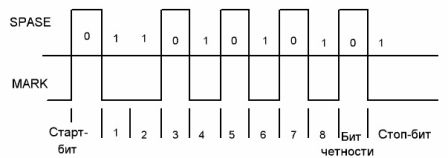
Picture 1.
For CONTROL circuits, a positive voltage corresponds to a logical unit (on), and a negative voltage to a logical zero (off). All measurements are made with respect to the SG contact (information ground).
The actual data transfer is performed in start-stop mode by a sequential asynchronous method. The application of this method does not require the transmission of any additional synchronization signals, and, consequently, additional lines for their transmission.
Information is transmitted in bytes (eight bit binary number), which are complemented by overhead information. Firstly, it is a start bit (a bit is one binary bit), after which eight data bits follow. Directly behind them comes the parity bit and after all that, the stop bit. There can be several stop bits. (A bit is an abbreviation for English binary digit - a binary digit).
In the absence of data transmission, the line is in the state of a logical unit (voltage in the line is -3 ... 12V). The start bit starts transmission, setting the line to a logic zero level. A receiver connected to this line, having received the start bit, starts a counter that counts the time intervals intended for the transmission of each bit. At the right time, as a rule, in the middle of the interval, the receiver gates the state of the line and remembers its state. This method reads information from the line.
In order to verify the reliability of the received information, the parity check bit is used: if the number of units contained in the transmitted byte is odd, then one more unit is added to them - the parity check bit. (However, this unit can add bytes on the contrary until it is odd. It all depends on the accepted data transfer protocol).
On the receiver side, the parity is checked and if an odd number of units is detected, the program will fix the error and take measures to eliminate it. For example, it may request a retransmission of the failed byte. True, the parity check is not always activated, this mode can simply be turned off and the check bit in this case is not transmitted.
The transmission of each byte ends with stop bits. Their purpose is to stop the operation of the receiver, which, according to the first of them, goes to wait for the next byte to be received, more precisely, its start bit. The stop bit level is always logical 1, just like the level in the pauses between word transfers. Therefore, by changing the number of stop bits, you can adjust the duration of these pauses, which makes it possible to achieve reliable communication with a minimum duration.
The entire serial interface algorithm in the computer is performed by special controllers without the participation of a central processor. The latter only configures these controllers for a certain mode, and uploads data to it for transmission, or receives received data.
When working with a modem, the RS-232C interface provides not only data lines, but also additional control signals. In this article, considering them in detail simply does not make sense, since only two of them are used in the proposed adapter circuit. This will be discussed below in the description of the circuit diagram.
In addition to RS-232C, the serial interface IRPS (Radial Interface with Serial Communication) is very widespread. His second name is Current Loop. This interface logically corresponds to RS-232C: the same serial data transmission principle and the same format: start bit, data byte, parity bit and stop bit.
The difference from RS-232C is only in the physical implementation of the communication channel. Logical levels are transmitted not by voltages, but by currents. A similar scheme allows you to organize communication between devices located at a distance of one and a half kilometers.
In addition, the “current loop”, unlike the RS-232C, has no control signals: by default, it is assumed that they are all in an active state.
So that the resistance of long communication lines does not affect signal levels, the lines are powered through current stabilizers.
The figure below shows a very simplified diagram of the current loop interface. As already mentioned, the line is powered from a current source, which can be installed either in the transmitter or in the receiver, which does not matter.
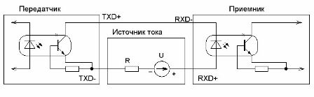
Figure 2
A logical unit in the line corresponds to a current of 12 ... 20 mA, and a logical zero corresponds to a lack of current, more precisely, no more than 2 mA. Therefore, the output stage of the transmitter "current loop" is a simple transistor switch.
A transistor optocoupler is used as a receiver, which provides galvanic isolation from the communication line. In order for the communication to be two-way, one more same loop is necessary (two communication lines), although transmission methods are known in two directions and on one twisted pair.
The serviceability of the communication channel is very simple to check if you include a milliammeter in the gap of either of the two wires, preferably a dial meter. In the absence of data transmission, it should show a current close to 20 mA, and if data is being transmitted, then slight twitching of the arrow can be noticed. (If the transmission speed is not high, but the transmission itself is in packets).
The circuit diagram of the RS-232C adapter - “Current loop” is shown in Figure 3.

Figure 3. Schematic diagram of the RS-232C adapter - “Current loop” (clicking on the picture will open the diagram in a larger format)
In the initial state, the signal Rxd is in the state of a logical unit (see Figure 1), that is, the voltage on it is -12 V, which leads to the opening of the transistor optocoupler DA2, and with it the transistor VT1, through which a current of 20 mA flows through the current stabilizer and the optocoupler LED controller receiver, as shown in Figure 4. For the "current loop", this is the state of the logical unit.
When the signal Rxd takes a value of logical zero (voltage + 12V), the optocoupler DA2 closes and the transistor VT1 is connected with it, so the current becomes zero, which fully complies with the requirements of the "Current loop" interface. Thus, serial data will be transferred from the computer to the controller.
Data from the controller to the computer is transmitted through the optocoupler DA1 and transistor VT2: when the current loop line is in the logical unit state (current 20 mA), the optocoupler opens the transistor VT2 and a voltage of -12 V appears at the input of the RS-232C receiver, which, according to Figure 1, is the logical level units. This corresponds to a pause between data transfers.
When the current loop is zero (logical zero) on the communication line of the current loop, the optocoupler DA1 and transistor VT2 are closed at the input RxD, there will be a voltage of + 12V - corresponds to the level of logical zero.
In order to receive bipolar voltage at the RxD input, the signals DTR Data Terminal Ready and RTS Request to Send are used.
These signals are designed to work with the modem, but in this case they are used as a power source for the RxD line, so an additional source is not required. Programmatically, these signals are set in this way: DTR = + 12V, RTS = -12V. These voltages are isolated from each other by diodes VD1 and VD2.
For the independent manufacture of the adapter, you will need the following details.
List of items.
DA, DA = 2xAOT128
R1 = 1x4.7K
R2, R4 = 2x100K
R3 = 1x200
R6, R7 = 2x680
R8, R9, R10 = 3x1M
VD1, VD2, VD3, VD4, VD5 = 5xKD522
VT1, VT2 = 2xKT814G
If, instead of domestic AOT128 optocouplers, import 4N35 is used, which is most likely in the current radio market, the resistors R2, R4 should be set to 820K ... 1M.
The connection of the controller to the computer is shown in Figure 4. (Current stabilizers are located in the controller).

Figure 4
Figure 5 shows the finished adapter board.

Figure 5 Rmotherboard adapter
Connecting to a computer is done using a standard DB-9 connector, (female part) using a standard serial cable.
Sometimes, similar in appearance cables from the UPS (uninterruptible) remain. They have a specific wiring and are not suitable for connecting an adapter.
The current loop interface lines are connected using terminal clamps.
Boris Aladyshkin
See also at bgv.electricianexp.com
: