Categories: Featured Articles » Practical Electronics
Number of views: 43018
Comments on the article: 3
Simple logic probe
 Logic probe scheme for troubleshooting digital circuits, a description of its capabilities and methods of working with a probe.
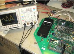
It is well known that for the repair and establishment of electronic digital circuits it is necessary oscilloscope. Of course, now those days are gone when it was necessary to repair large computers in factories. But there were devices for various purposes on microcontrollers, specialized microcircuits, a large number of devices using digital microcircuits with a small degree of integration (not all enterprises and organizations managed to acquire modern imported equipment).
It is impossible to see the processes occurring in pulsed circuits with a conventional avometer and draw conclusions about the operation of the circuit as a whole. But the oscilloscope is not always at hand. In this case, the described logical probe can be of invaluable help.
A lot of similar devices have been described in the literature, and all of them with the same purpose still have completely different parameters: there are some that are simply inconvenient and incomprehensible to work with. Such probes were produced by domestic industry until the end of the last century.
For many years I had the opportunity to use a logical probe, the design of which is described below. The circuit has proven reliable and easy to use.
The main difference between this scheme and similar ones is the minimum number of parts with fairly wide capabilities. One of the features of the circuit is the presence of a second input, which sometimes allows you to do without a two-beam oscilloscope.
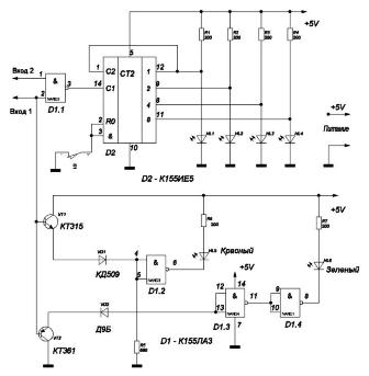
Logic Probe Electrical Schematic
Description of the concept.
The power supply of the probe (+ 5V) is carried out from the circuit under test.
The studied signal is fed to the base of the input transistors VT1, VT2, designed to increase the input resistance of the device. Further, through the diodes VD1, VD2, the signal passes to logic elements D1.2, D1.3, D1.4, which illuminate the red and green LEDs.
Techniques for working with a probe.
The glow of the red LED indicates the presence of 1 logical unit at the input, and green - logical zero.
For the described probe, the logic zero voltage is 0 ... 0.4V, and the logical unit voltage is 2.4 ... 5.0V. If input 1 of the probe is not connected anywhere, both LEDs are off.
In the case when input 1 is connected to the circuit under test, and both LEDs are off, we can assume that there is a malfunction. This level is called "gray."
In addition to displaying logical levels of zero and one, the probe can also indicate the presence of pulses. For these purposes, a binary counter D2 is used, to the outputs of which the yellow LEDs HL1 ... HL4 are connected.
With the arrival of each pulse, the state of the counter increases by one. If the pulse repetition rate is small, then you can see the blinking counter LEDs, even if the pulse lasting several microseconds appears once a second or even less. Such a process can be fixed only with the help of a storage oscilloscope - a device quite expensive and rare.
When pulses follow at a high frequency, it seems that the LEDs HL1 ... HL4 glow continuously, although they are actually lit by pulses.
By the nature of the glow of the red and green LEDs, one can approximately evaluate the shape of the pulses. If the brightness of both LEDs is the same, then the pulse duration (log. 1) is equal to the pause duration (log. 0). A more intense glow of the red LED indicates that the pulse duration (log. 1) is longer than the pause duration (log. 0) and vice versa.
The ratio of the pulse to the pause can be such that the glow of only one LED is noticeable. But if at the same time the counter continues to count, then there are pulses.The button S1 is used to reset the counter: if after pressing and releasing the LEDs HL1 ... HL4 they go out and do not change their state, then there are no pulses, and the probe simply displays a logical level of zero or one.
A few words about the details.
Diodes VD1, VD2 can be replaced by any pulsed low-power diodes. Only in this case it should be remembered that VD1 must be silicon, and VD2 must be germanium: it is they who separate the level of zero and unity. Transistors can be with any alphabetic indexes, or replaced with KT3102 and KT3107.
Chips can be replaced by imported analogues: K155LA3 on SN7400N, and K155IE5 on SN7493N.
The design of the probe is arbitrary, but it is best done using a printed circuit in the form of a probe, placed in a suitable plastic case.
When working with a probe, you must carefully monitor so as not to connect power to circuits with a voltage of more than 5V, and also not to touch such circuits with a measuring probe. Such touches lead to the repair of the device.
Boris Aladyshkin
See also at bgv.electricianexp.com
:

