Categories: Featured Articles » Practical Electronics
Number of views: 298,311
Comments on the article: 16

Simple converter 12V to 220V 50Hz


Simple converter 12V to 220V 50HzThe article describes a converter circuit made on a modern element base, containing a minimum number of parts and allowing to obtain significant power in the load.

For many years now, on the pages of radio engineering publications, schemes have been published that allow car battery get an alternating voltage of 220V to power various equipment in the "field" conditions. Of course, you can always buy a voltage converter 12 220, but it’s much more interesting to do a voltage converter with your own hands.

The circuitry of such converters is quite simple: the master oscillator controls the operation of powerful output transistors that “swing” the output transformer. The generator, as a rule, was run on microcircuits of a small degree of integration K155, K561 and the like, and contained from two to four cases.

To coordinate powerful output transistors with these microcircuits, it was necessary to introduce additional stages on transistors of small and medium power. The output transistors, which were most often used KT819GM, had to put on a fairly large radiator.

The modern elemental base allows us to significantly simplify such schemes. The proposed scheme, in comparison with the just described, contains a minimum number of parts.

A specialized chip KR1211EU1 is used as a master oscillator. By the way, the domestic microcircuit does not have foreign analogues.

As the output keys, powerful IRL2505 field effect transistors are used, which are often used in various automotive devices.

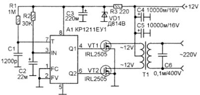
KR1211EU1 has two outputs - direct and inverse. These are conclusions 4 and 6 respectively. The signal level at these outputs is sufficient for direct control output transistors: Transistors open with high-level pulses. Moreover, between them the microcircuit itself forms a pause (low level), which for a certain period of time, sometimes called “dead time”, keeps both transistors closed. This is done in order to exclude the appearance of through current when opening both keys at once.

Electrical schematic diagram of a 12V to 220V 50Hz converter

Electrical schematic diagram of a 12V to 220V 50Hz converter

The required frequency of the generator is set by the chain R1 - C1, the circuit R2 - C2 is used as a starting.

Pin 1 of the microcircuit allows you to disable pulse generation, for which a high level should be applied to it. This property can be used for remote control or for protection. In this circuit, these functions are not used, so pin 1 is simply connected to a common wire.

The output push-pull stage is made on a transformer T1 and key transistors VT1, VT2, which are used as IRL2505. The open channel resistance of these transistors is 0.008 ohms. This is commensurate with mechanical contact resistance, therefore, the power dissipated by the transistor in the open state is small, even at high currents, which allows in some cases to abandon the use of radiators.

Direct current IRL2505 up to 104A, pulse 360A. Such parameters make it possible to use an output transformer with a power of up to 1000W, at which it is possible to remove up to 400W at a voltage of 220V.

The advantage of this converter is that you can use any ready-made transformer that has two output windings for 12V. The power of the transformer depends on the load and should be 2.5 times higher: suppose that the load power is 30W. Then the power of the transformer must be at least 30 * 2.5 = 75W.

With an output power of not more than 200 W, transistors can not be installed on radiators.


About the details. Microcircuit A1 receives power from the parametric stabilizer R3, VD1, C3.As a zener diode VD1, anyone with a stabilization voltage of 8 ... 10V is suitable.

Electrolytic capacitors imported. If there are no capacitors at 10000 mkf, (C4, C5) they can be replaced with 4700 mkf capacitors, turning them on in parallel.

Capacitor C6 serves to suppress the output of high-frequency pulses. It can be of the type K-73-17 or a similar import.

During installation, one should not forget that already at a power of 400 W, the current consumed from the battery through the 12V circuit can reach 40A, so the wires for connecting to the battery should be of sufficient cross section and the shortest possible length.

Boris Aladyshkin

Practical Electrical Engineering and Electronics

See also at bgv.electricianexp.com:

  • Schemes of amateur frequency converters
  • Timer 555. Voltage Converters
  • Step up power regulator for soldering iron
  • Bipolar and field effect transistors - what is the difference
  • How to choose an analog transistor

  •  
     
    Comments:

    # 1 wrote: | [quote]


    And with this device, how long will the battery last for me, for example, to use only a laptop with 45 ampere acb and can I connect it to the cigarette lighter or directly to the battery?

     
    Comments:

    # 2 wrote: 1 | [quote]


    10 hours is enough if the battery is not "dead". It is possible and a cigarette lighter, I think there will be 3-4 amperes on a laptop

     
    Comments:

    # 3 wrote: | [quote]


    Is it possible to use IRFZ44V transistors in this circuit, and really really want to put them in parallel, 2 pieces per channel without major alterations? Did you see such a circuit with parallel transistors in an uninterruptible system, or are your transistors more powerful than I have proposed?

     
    Comments:

    # 4 wrote: | [quote]


    It is possible in this circuit to use 2 identical transfrara connecting for example 12-volt windings of the afterburner, and secondary secondary 220 parallel. Will the circuit work?

     
    Comments:

    # 5 wrote: Mitya | [quote]


    And what kind of transformer? can you describe? pliz!

     
    Comments:

    # 6 wrote: | [quote]


    Quote: Mitya
    And what kind of transformer? can you describe? pliz!

    take from the old tube TV (they have a power of 150-200 watts) - they are U-shaped - it is convenient to disassemble and rewind, rewind the secondary windings - they are on top - you do not have to wind a lot.

     
    Comments:

    # 7 wrote: Boris Aladyshkin | [quote]


    A similar converter was required to power the engraving machine on stone, so special power was not required. The main requirement was the output frequency close to 50Hz at a voltage of 220V. The transformer was used with a purchase power of approximately 40 - 50W, the battery from the uninterruptible power supply 7A / H. But, if much more power is required, then, as Roman writes, it is quite possible to use a transformer from tube televisions. In general, it is possible to use a transformer with a power of up to 1000W, only transistors will need to be installed on radiators with an area of ​​at least 400 - 500 square centimeters.

    Michael, the IRFZ44V transistor has the following data: drain-source voltage 60V (55), drain current 55A (104), open channel resistance 0.016Ω (0.008). In parentheses are the parameters for IRL2505. It turns out that it’s twice as powerful. Therefore, you will have to turn them on (IRFZ44V) in pairs: the drains and sources simply turn on in parallel, and the gates through resistors with a resistance of 30 ... 56 Ohms.

    It is possible in this circuit to use 2 identical transfrara connecting for example 12-volt windings of the afterburner, and secondary secondary 220 parallel. Will the circuit work?

    Probably not, because when the output windings are connected in parallel, the output voltage from one winding will be transferred to another, and will not go to the load. And then, is it really so hard to find a suitable transformer?

     
    Comments:

    # 8 wrote: | [quote]


    And if on kr1211eu1 to assemble a generator for 20 kHz trans change for ferit winding on a ferrite for 4 turns why irl 2505 burns out? Or do you need a chip kr1211eu1a?

     
    Comments:

    # 9 wrote: Boris Aladyshkin | [quote]


    sergey, enough details about using a transformer on ferrite can be found in the article "Interesting ideas and developments" - kulibin.ucoz.com/publ/skhemy/ehlektronika_v_bytu/preobrazovatel_12_220v_na_kr121
    1eu1 / 3-1-0-19

    The article suggests the use of off-the-shelf transformers from AT and ATX computer power supplies. There is no difference. Probably, this option is the simplest and most correct: you do not need any calculations, search for ferrite cores, painfully winding wires manually. Transformers turn on the other way around: the secondary winding at 12 V becomes primary, the output voltage is removed from the former primary winding. In idle mode, at the output, such a source gives about 400V, under load (two energy-saving lamps of 20W each) 223V. There, in the article, there are photographs, recommendations for calculating the frequency, and the use of transistors, including IRL2505.

     
    Comments:

    # 10 wrote: | [quote]


    Is it possible to make a 10 kW 12-220 V converter? It is clear that the input current will be huge, but what circuit should be in order to get 10 kW at the output for the load?

     
    Comments:

    # 11 wrote: | [quote]


    Dmitriy,
    the circuit does not need to be changed ... for more power, more powerful transistors are needed ... but that's not all ... so that they CLOSE normally without falling edges, since no one canceled the shutter capacity - you just need to use the driver to control these same shutters)))

     
    Comments:

    # 12 wrote: | [quote]


    Who has such a chip - KR1211EU1. SEND BY MAIL, PLIZ.

     
    Comments:

    # 13 wrote: | [quote]


    Does such a converter output a correct sine wave? I wanted to use it as a backup power source for a circulation pump (power 100-200 W). But the asynchronous pump motor will burn out in half an hour if it is powered instead of the correct sine wave by "step approximation", for example, such as that given out by computer UPS.

     
    Comments:

    # 14 wrote: | [quote]


    Sorry, maybe for a silly question, do you need to wind two windings of 12 volts or 6 volts?

     
    Comments:

    # 15 wrote: | [quote]


    Vitaly, a transformer is suitable, which has 2 windings of 12 volts, with a tap in the middle. That is, the voltage at the edges of the windings will be 24 V, and between the middle terminal and any of the windings 12 V. So the windings must be wound 2x12 in.

     
    Comments:

    # 16 wrote: | [quote]


    But what if we take four such IRL2505 transistors and connect their leads in parallel so that the load is evenly distributed. So you can increase the output power.

    And what is the output waveform? (Sinusoid or not).