Categories: Featured Articles » Practical Electronics
Number of views: 72706
Comments on the article: 10
Step up power regulator for soldering iron
 Sometimes, with a reduced voltage in the network or soldering of massive parts, it becomes simply impossible to use a soldering iron. Here the power regulator for a soldering iron can come to the rescue.
There are many guides and articles on how to perform high-quality soldering. In addition to the use of high-quality fluxes and solders, the quality of soldering is to a large extent dependent on temperature soldering iron.
There are many schemes for regulating the power of a soldering iron: from the simplest inclusion of a diode in series with a soldering iron to very complex temperature-stabilizing devices. But, unfortunately, all such devices can only work on lowering the power, i.e. power regulation occurs from 0 ... 100% or 50 ... 100%.
But sometimes the power of the soldering iron is not enough, for example, when the voltage in the network is lower than 220V, or you need to warm large parts. More often this happens when soldering parts from old boards. For such cases, the power regulator described below is simply irreplaceable.
The idea itself is not new: the load (soldering iron) is powered by a rectified mains voltage, which, after smoothing by an electrolytic capacitor, has a value of 1.41 times more than current voltage. At network voltage 220V The rectified DC voltage across the capacitor will be 310V. Even if the voltage in the network drops to 170V, after the rectifier there will be 170 * 1.41 = 239.7V, which will allow the soldering iron to be heated to the optimum temperature.
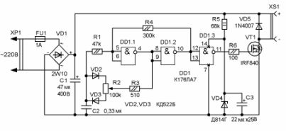
Electrical schematic diagram of a step-up power regulator for a soldering iron
Description of the power regulator circuit. The input rectifier is made on the bridge VD1 and electrolytic capacitor C1, the operating voltage of which must be at least 400V.
The output stage of the regulator is made on a key field-effect transistor IRF840, the power of which is enough to work with a soldering iron up to 65W even without a radiator. In practice, it was noticed that high power soldering irons do not need such an up-regulator. Even with a reduced voltage in the network, they heat up above the required temperature.
The key transistor is controlled from a PWM generator made on a DD1 chip. Capacitor C2 sets the frequency of the generator.
On parts R5, VD4, C3, a parametric type stabilizer is made, from which the DD1 chip is powered.
The VD5 diode is installed in the case of switching on a load having an inductive nature in order to protect the output transistor from surges of self-induction voltage. If the design will be used only with a soldering iron, then it can be omitted.
Design and details of a step-up power regulator for a fishing lanyard. The design of the regulator is arbitrary, for example, it can be performed by hinged installation directly in the socket housing. In this case, the parts must be small.
All 0.125W resistors, with the exception of R5, whose power is at least two watts. It may be necessary to select its face value when setting so that the supply voltage of the microcircuit is 11 ... 12V.
Possible part replacement. The rectifier bridge can be made of diodes with a current of at least 2A, the microcircuit can be replaced with K561LA7. As the output transistor, the IRF740 is quite suitable.
With working parts and no errors in installation, the soldering iron power regulator circuit does not need to be adjusted.
Boris Aladyshkin
See also at bgv.electricianexp.com
:

