Categories: Electrical Reviews
Number of views: 14616
Comments on the article: 0
Universal SkyRC iMax B6 mini charger for any battery
I present an overview of the popular SkyRC iMax B6 mini charging.
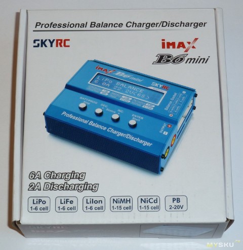
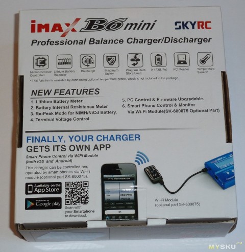
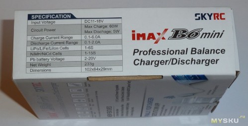
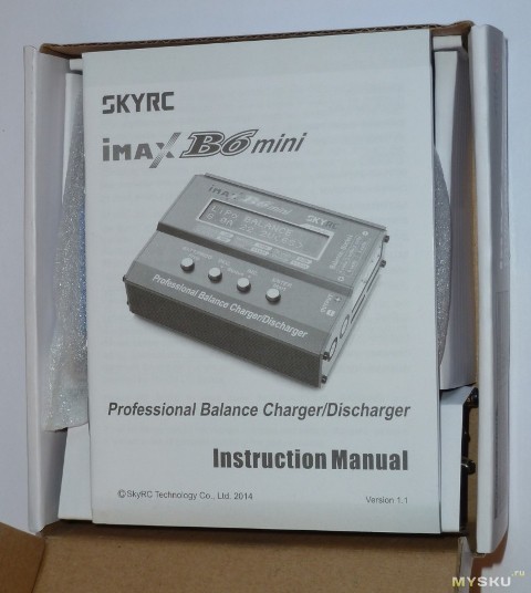
The instruction is in English only.
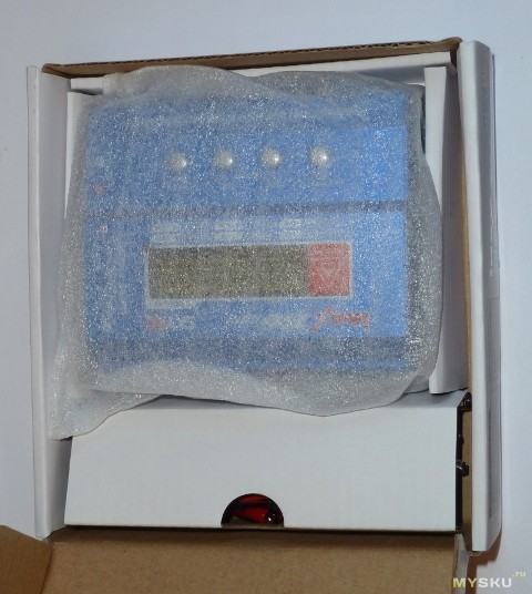
The device itself is wrapped in a soft bag.
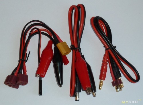
Cables included.
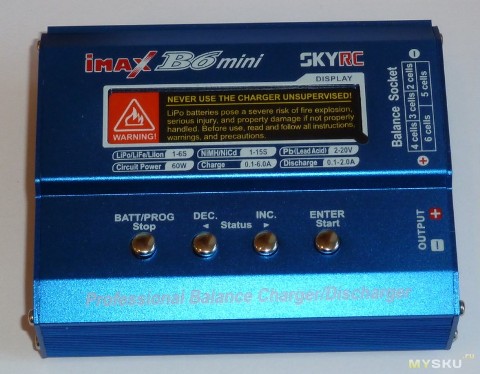
A warning tag is pasted on the screen stating that if something went wrong - they are to blame, there was nothing left unattended :)
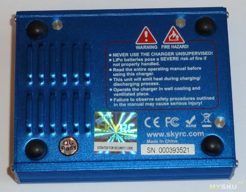
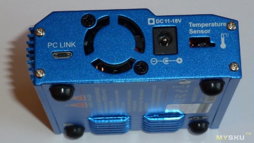
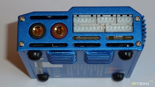
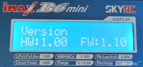
The initial version of firmware is V1.10.
The firmware was updated on V1.12 - it added the ability to charge lithium without balancing, which can sometimes be useful, and sometimes dangerous.
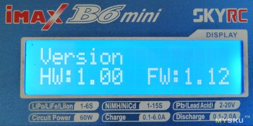
It was not possible to flash under Win8.1 - it was flashing under Wn7 with language switching to English. As it turned out later, it was necessary to run the program on behalf of the Administrator. Under WinXP, the program refused to start. How to work with this charge has been written many times in other reviews (links below) and it makes no sense to repeat it, inflating the review, so I will try to tell only new information.
Disassembling charging is very simple - on 8 screws from the ends.

Small non-standard cooling fan 25x25x7mm at 15V.
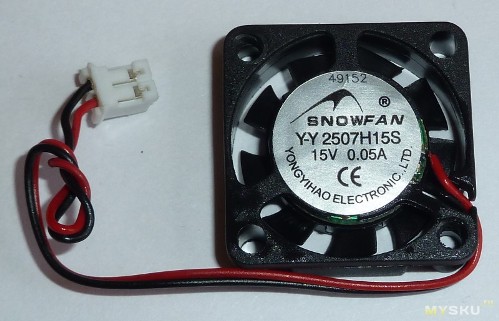
The fan is so rare that even the manufacturer’s catalog didn’t have it, apparently they make it on special order ...
The temperature of turning on the fan is 40g; the shutdown is 35g; it works by blowing hot air. When heating, the fan turns on immediately at full input voltage and, accordingly, its rotation speed is determined by the input voltage. With a voltage of more than 15V, the fan will overload and make a lot of noise.
Next, the board is unscrewed from the bottom cover.
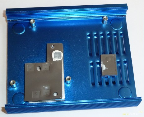
And here she is, beauty :)
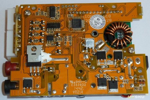
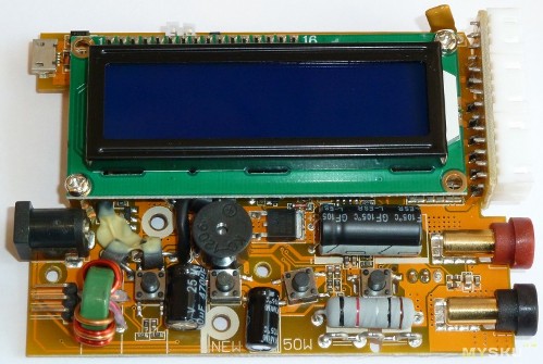
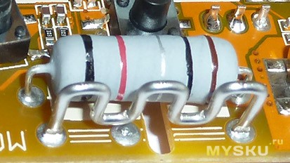
Collected neatly, high-quality soldering, flux almost washed. Normal wire current-measuring shunts are 0.03 Ohm for monitoring the charge circuit current and 0.1 Ohm for monitoring the discharge circuit current.
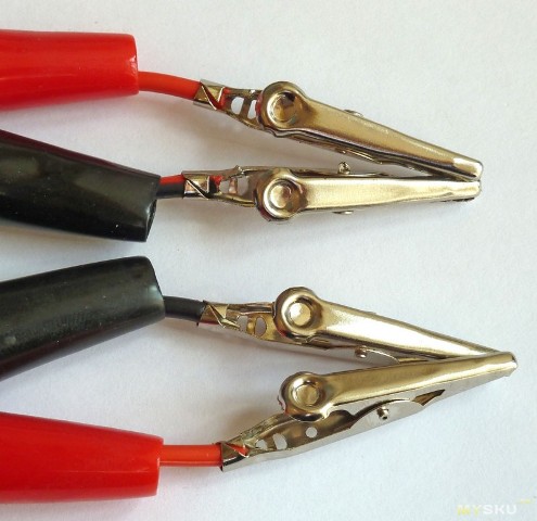
Complete wires of normal quality, crocodiles are soldered.
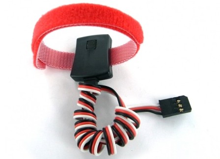
An external temperature sensor can be connected to the charging: branded SK-600040-01
or homemade based on LM35DZ
The internal temperature sensor is located directly near the discharge field effect transistor.
Charging takes into account the voltage drop on the connecting wires during the flow of charge and discharge currents (parameter Resistance Set). The value of the parameter is saved even when the default settings are reset. I do not recommend mindlessly changing this value.
The banana-T + T-crocodile connecting wires have a real total resistance of 38mOhm, and the optimal value of Resistance Set = 85
Some software glitches:
-
there is no possibility to adjust the charge and discharge voltage on Pb batteries;
-
lithium in standard charging mode charges the battery to a current decrease of 0.1A or less, regardless of the setting of the charging current, which is incorrect, because final charging current should be about 10% of the set current;
-
in NiCd and NiMH Auto Charge modes, the charging current may exceed the set limit, for example, set 0.2A, and the charge goes 0.6A;
-
in NiCd and NiMH modes, the delta catches are very unstable and significantly higher than specified in the settings - this can lead to overcharging of the batteries.
When the minimum delta of 4mV / Cell (Default) was set in NiCd and NiMH modes, charging turned off when the voltage dropped by 10-20mV. Sometimes the delta generally skips and charges the battery until it is very hot :(
So why is this happening? The fact is that the controller is physically unable to catch the difference of 4-5mV due to the presence of a voltage divider of 1: 7.47 at the input and 12bit ADC (the discrete is almost 10mV).
Therefore, when charging NiCd and NiMH, you must either limit the capacity to be filled, or use an external temperature sensor.
Schedule of correspondence between the set and real discharge current in Pb mode at a voltage of 2-2.5V:
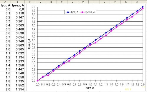
Turning on the fan causes an increase in the output current by 0.01A.
The error in setting low discharge currents is very large - the current is very underestimated (especially in the range of 0.2-0.8 A).That is why the displayed battery capacity when discharging often exceeds the flooded capacity. It seems that software calibration of the discharge current was not performed at all. For lithium, the optimal discharge current with a minimum error is obtained at a current of 1.0 A, while the measured capacity will be overstated by 3.5%.
In Fast mode, lithium charges until the charging current drops to 50% or less for 1.5 minutes. In this case, the battery does not really fully charge (up to about 95%).
Lithium in Charge mode charges until the charging current drops to 0.1A or less for 1.5 minutes, regardless of the setting of the charging current.
LiPo charges up to 4.20V per cell (4.18-4.25V can be adjusted), discharges up to 3.20V per cell (3.0-3.3V can be adjusted).
Li-Ion charges up to 4.10V per cell (4.08-4.20V can be adjusted), discharges up to 3.10V per cell (2.9-3.2V can be adjusted).
Li-Fe charges up to 3.60V per cell (3.58-3.70V can be adjusted), discharges up to 2.80V (2.6-2.9V can be adjusted).
Lead charges up to 2.4V per cell (without adjustment) and a current drop of 10% or less for 10 seconds.
The final lead discharge voltage is 1.8V per cell (without adjustment) and without delay.
In the NiCd and NMH charging mode, the charging voltage is supplied without checking the battery connection, and at the same time, up to 26V voltage appears at the output. Short circuit protection does not work - be careful!
In this mode, charging every 30 sec disables the charging current for 2 sec for more precise control of the voltage on the batteries. It is this tension that is being shown.
The measured input voltage is slightly overstated - at real 12.00V it shows 12.18V.
When the input voltage is less than 10V, DC IN TOO LOW is displayed on the screen.
When the input voltage is more than 18V, DC IN TOO HI (High input voltage) is displayed on the screen.
The maximum output power of the charging is highly dependent on the magnitude of the input voltage. It produces full power only with an input voltage of 15V or more. No wonder the native PSU has a voltage of exactly 15V.
A plot of the actual output power over the entire allowable range of input voltage values:
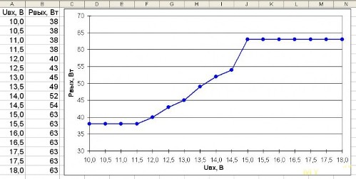
The maximum charge power of 63W exceeds the declared 60W because the actual current exceeds the displayed value.
Unfortunately, alternative firmware is not yet available.
Self calibration is also not yet available.
Conclusions: without a doubt, charging the B6 mini is very interesting and, despite the shortcomings, pleased with its work. The potential of this charge is so far limited by the desire of the manufacturer, who is in no hurry to correct at least software errors.
See also at bgv.electricianexp.com
:
