Categories: Featured Articles » Electrician Secrets
Number of views: 23464
Comments on the article: 1
Single-phase connection of a three-phase motor
Asynchronous motors are widely used in industry due to the relative simplicity of design, good performance, ease of control.
Such devices often fall into the hands of a home master and he, using knowledge of the basics of electrical engineering, connects such an electric motor to work from a single-phase 220 volt network. Most often it is used for emery, wood processing, grain grinding and other simple work.
Even on individual industrial machines and mechanisms with drives there are samples of various engines that can operate on one or three phases.
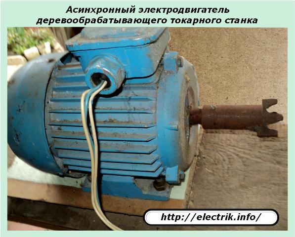
Most often, they use a capacitor start, as the most simple and acceptable, although this is not the only method known to most competent electricians.
The principle of operation of a three-phase motor
Industrial asynchronous electrical devices of 0.4 kV systems are available with three stator windings. Voltages are applied to them, shifted by an angle of 120 degrees and causing currents of a similar shape.
To start the electric motor, the currents are directed so that they create a total rotating electromagnetic field that optimally acts on the rotor.
The stator design used for these purposes is represented by:
1. housing;
2. core magnetic core with three windings laid in it;
3. terminal connections.
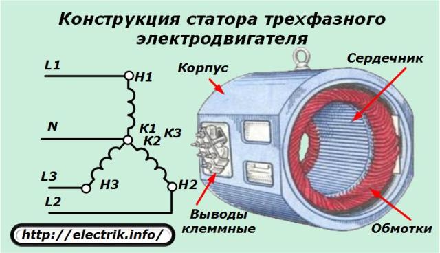
In the usual version, the insulated wires of the windings are assembled according to the star scheme due to the installation of jumpers between the terminal screws. In addition to this method, there is also a connection called a triangle.
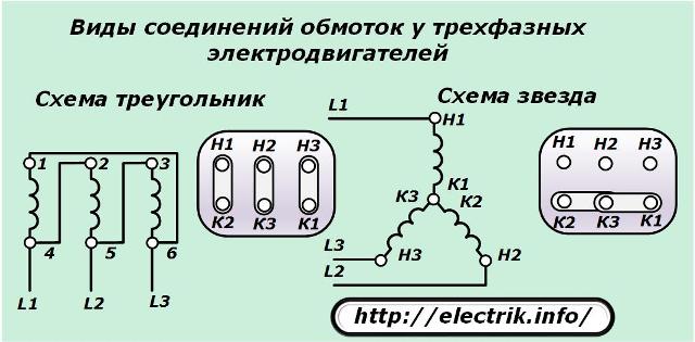
In both cases, the direction of the windings is assigned: the beginning and end associated with the method of installation - winding during manufacture.
The windings are numbered in Arabic numerals 1, 2, 3. Their ends are indicated by K1, K2, K3, and the beginning - H1, H2, H3. For certain types of engines, this marking method can be changed, for example, C1, C2, C3 and C4, C5, C6 or other symbols or not used at all.
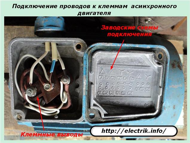
Correctly applied marking simplifies the connection of power wires. When creating a symmetrical voltage arrangement on the windings, the creation of rated currents that ensure optimal operation of the electric motor is ensured. In this case, their shape in the windings fully corresponds to the applied voltage, repeats it without any distortion.
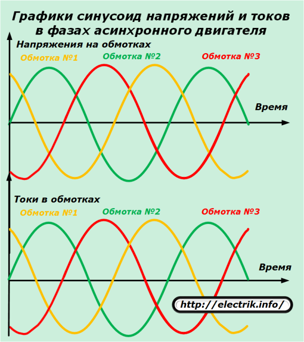
Naturally, it should be understood that this is a purely theoretical statement, because in practice the currents overcome various resistances and slightly deviate.
The visual perception of the processes helps the image of vector quantities on the complex plane. For a three-phase motor, the currents in the windings created by the applied symmetrical voltage are depicted as follows.
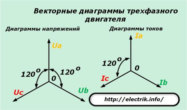
When the electric motor is powered by a system of voltages with three uniformly spaced angles and equal in magnitude vectors, the same symmetrical currents flow in the windings.
Each of them forms an electromagnetic field, the induction force of which induces its own magnetic field in the rotor winding. As a result of the complex interaction of the three fields of the stator with the rotor field, the rotational motion of the latter is created, and the creation of maximum mechanical power that rotates the rotor is ensured.
Principles of connecting a single-phase voltage to a three-phase motor
For a full connection to three identical stator windings, separated by an angle of 120 degrees, two voltage vectors are missing, there is only one of them.
You can apply it in just one winding and make the rotor rotate. But, to effectively use such an engine will not work.It will have a very low output power on the shaft.
Therefore, the problem arises of connecting this phase so that it creates a symmetrical system of currents in different windings. In other words, a single-phase to three-phase voltage converter is needed. A similar problem is solved by different methods.
If we discard the complex schemes of modern inverter installations, then we can implement the following common methods:
1. use of capacitor start;
2. the use of chokes, inductive resistances;
3. the creation of various directions of currents in the windings;
4. A combined method with equalization of phase resistances for the formation of the same amplitudes at the currents.
Briefly examine these principles.
Current deviation when passing through a capacitance
The most widely practiced capacitor launch, which allows to divert the current in one of the windings by connecting capacitive resistance, when the current is 90 degrees ahead of the applied voltage vector.
As capacitors, metal-paper constructions of the MBGO, MBGP, KBG series and the like are usually used. Electrolytes are not suitable for passing alternating current, quickly explode, and the schemes for their use are complex, low reliability.
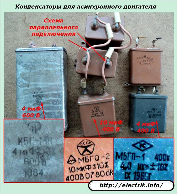
In this circuit, the current differs in angle from the nominal value. It deviates only 90 degrees, not reaching 30about (120-90=30).
Current deviation when passing through inductance
The situation is similar to the previous one. Only here the current lags the voltage by the same 90 degrees, and thirty lacks. In addition, the design of the inductor is not as simple as that of a capacitor. It must be calculated, assembled, adjusted to individual conditions. This method is not widespread.
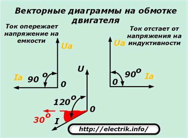
When using capacitors or chokes, the currents in the motor windings do not reach the required angle by the thirty-degree sector, shown in red in the picture, which already creates increased energy losses. But you have to put up with them.
They interfere with the creation of a uniform distribution of induction forces, and create an inhibitory effect. It is difficult to accurately assess its effect, but with a simple approach to dividing the angles, a (25/120 = 1/4) loss of 25% is obtained. However, is it possible to think so?
Current deviation by applying reverse polarity voltage
In the star circuit, it is customary to connect a phase voltage wire to the input of the winding, and a neutral wire to its end.
If two separated by 120about phase to apply the same voltage, but to separate them, and in the second to reverse polarity, the currents will shift in angle relative to each other. They will form electromagnetic fields of different directions, affecting the generated power.
Only with this method the angle deviation of currents by a small value is obtained - 30about.
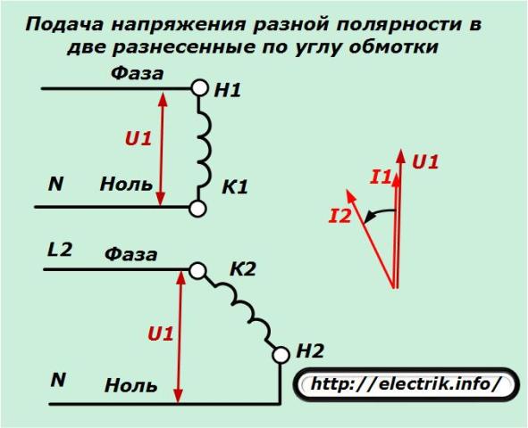
This method is used in individual cases.
Methods for the complex use of capacitors, inductances, polarity reversal of windings
The first three listed methods do not allow one to create an optimally symmetric deviation of currents in the windings. Always there is a skew in the angle relative to the stationary circuit provided for three-phase high-grade power supply. Due to this, the formation of opposing moments that inhibit the promotion, reduce efficiency.
Therefore, the researchers conducted numerous experiments based on different combinations of these methods in order to create a converter that provides the greatest efficiency of the three-phase motor. These schemes with a detailed analysis of electrical processes are given in special educational literature. Their study increases the level of theoretical knowledge, but for the most part they are rarely applied in practice.
A good picture of the distribution of currents is created in the circuit when:
1. direct winding phase is applied to one winding;
2. the voltage is connected to the second and third windings through a capacitor and inductor, respectively;
3. inside the converter circuit, the amplitudes of the currents are equalized by selecting reactances with unbalance compensation by active resistors.
I would like to pay attention to the third point, to which many electricians do not attach importance. Just look at the following picture and make a conclusion about the possibility of uniform rotation of the rotor with a symmetrical application of forces of the same and different in magnitude to it.
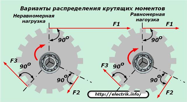
The complex method allows you to create a fairly complex scheme. It is very rarely applied in practice. One of the options for its implementation for a 1 kW electric motor is shown below.
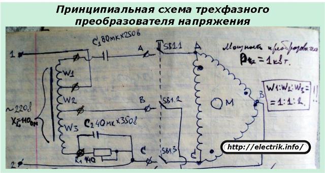
To make the converter, you need to create a complicated throttle. This requires time and material resources.
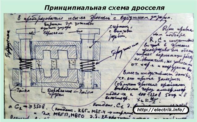
Also, difficulties will arise when searching for resistor R1, which will work with currents exceeding 3 amperes. He must:
-
have a power exceeding 700 watts;
-
cool well;
-
reliably isolate from live parts.
There are several more technical difficulties that will have to be overcome to create such a three-phase voltage converter. However, it is quite versatile, allows you to connect engines with a power of up to 2.5 kilowatts, ensures their stable operation.
So, the technical issue of connecting a three-phase asynchronous motor to a single-phase network is solved by creating a complex converter circuit. But, he did not find practical application for one simple reason that it is impossible to get rid of - the excessive consumption of electricity by the converter itself.
The power spent on creating a three-phase voltage circuit with such a design exceeds at least one and a half times the needs of the electric motor itself. At the same time, the total loads created by the power supply wiring are comparable to the work of old welding machines.
The electric meter, to the delight of electricity sellers, very quickly begins to transfer money from the homemaster’s wallet to the account of the energy supplying organization, and the owners do not like it at all. As a result, the complicated technical solution for creating a good voltage converter turned out to be unnecessary for practical use in the household, and also in industrial enterprises.
4 final conclusions
1. Technically, it is possible to use a single-phase connection of a three-phase motor. To do this, created a lot of different circuits with different elemental base.
2. To practically apply this method for long-term operation of drives in industrial machines and mechanisms is impractical due to the large loss of energy consumption created by extraneous processes leading to low system efficiency and increased material costs.
3. At home, the scheme can be used to perform short-term work on non-responsive mechanisms. Such devices can work for a long time, but at the same time, the payment for electricity increases significantly, and the power of a working drive is not provided.
4. For efficient operation of an induction motor, it is better to use a full three-phase power supply network. If this is not possible, then it is better to abandon this venture and acquire special single-phase electric motor appropriate power.
See also on this topic:Typical schemes for connecting a three-phase to a single-phase network
See also at bgv.electricianexp.com
:
