Fundamentals of Electrical Engineering for Computer Modding Lovers
 This article is for guidance only. The author is not responsible for any damage caused to the reader after reading it.
To begin with, everything in our computer works only because voltage, current is supplied to it :). Because of this, a number of processes and mechanisms are occurring, but we will not go deep. Where does this tension come from? Of course, from the Power Supply Unit (PSU). Its power is expressed in watts (watts).
Typically, power supplies go at least 250W, now they are increasingly installing a 300-350W power supply. Depends on its power, how many devices can be connected to your PC. In addition, there is such an indicator as the current strength in the circuit. But, as a rule, even in low-power PSUs, there is a rather large current strength and this issue should not bother you. Also, power supplies can be of 2 types: AT or ATX. AT was used on older systems; ATX now dominates. Well, let's get down to electrical work ...
 The need to establish electrical equipment is not as obvious as, say, the need to mount it. And the results of the adjustment are not so tangible, tangible as during installation. It would seem that it is simpler: apply voltage to the mounted electrical equipment and, by pressing a button, put it into action.
However, this can only be done in the simplest cases, for example, when the lighting in residential buildings is turned on; the vast majority of electrical circuits after installation are subject to adjustment.
First of all, the electrical equipment must be checked. This is explained by the fact that during the manufacture, transportation and installation of equipment and apparatus, their damage, deviations from the project, latent defects and, finally, just errors, especially when making connections in complex circuits, are possible. If you neglect the check, the result is likely to be a failure in work or a serious accident.
In commissioning, the sequence of operations is of great importance. First, they study the design and technical documentation for the electrical equipment of the launch complex, which is usually represented by the capital construction department of the customer enterprise. Then check the completeness of equipment delivery, compliance with its design. At the same time, the installers do not just get acquainted with the design solutions, but also identify shortcomings and errors of the circuit diagrams and correct the wiring diagrams if they are not consistent with the principal ...
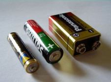 The author is most afraid that the inexperienced reader will not read the heading further. He believes the definition terms anode and cathode Every competent person knows that, solving a crossword puzzle, when asked about the name of the positive electrode, he immediately writes the word anode and everything fits in the cells. But there are not many things that are worse than half-knowledge.
Recently, in the Google search engine, in the “Questions and Answers” section, I even found a rule by which its authors suggest remembering the definition of electrodes. Here it is:
«Cathode - negative electrode anode is positive. And remembering this is easiest if you count the letters in words. IN cathode as many letters as in the word “minus”, and in anode respectively, as much as in the term “plus”. The rule is simple, memorable, one would have to offer it to schoolchildren if it were correct. Although the desire of teachers to put knowledge into the heads of students using mnemonics (the science of memorization) is very commendable. But back to our electrodes.
To begin with, we take a very serious document, which is the LAW for science, technology, and, of course, school. It "GOST 15596-82. SOURCES OF THE CURRENT CHEMICAL. Terms and Definitions".There, on page 3, you can read the following: “The negative electrode of a chemical current source is an electrode that, when discharged, is anode". The same thing, “A positive electrode of a chemical current source is an electrode that, when discharged, is cathode". (Terms are highlighted by me. BH). But the texts of the rule and GOST contradict each other. What is the matter? ...
Hall effect and sensors based on it
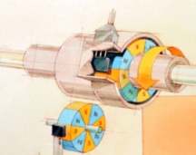 The Hall effect was discovered in 1879 by the American scientist Edwin Herbert Hall. Its essence is as follows. If a current is passed through a conductive plate and a magnetic field is directed perpendicular to the plate, then the voltage appears in the direction transverse to the current (and the direction of the magnetic field): Uh = (RhHlsinw) / d, where Rh is the Hall coefficient, which depends on the material of the conductor; H is the magnetic field strength; I is the current in the conductor; w is the angle between the direction of the current and the magnetic field induction vector (if w = 90 °, sinw = 1); d is the thickness of the material.
The Hall sensor has a slotted design. A semiconductor is located on one side of the slot, through which current flows when the ignition is turned on, and on the other hand, a permanent magnet.
In a magnetic field, moving electrons are affected by a force. The force vector is perpendicular to the direction of both the magnetic and electric components of the field.
If a semiconductor wafer (for example, from indium arsenide or indium antimonide) is introduced into a magnetic field through induction into an electric current, then a potential difference arises on the sides, perpendicular to the direction of the current. Hall voltage (Hall EMF) is proportional to current and magnetic induction.
There is a gap between the plate and the magnet. In the gap of the sensor is a steel screen. When there is no screen in the gap, a magnetic field acts on the semiconductor plate and the potential difference is removed from it. If there is a screen in the gap, then the magnetic lines of force close through the screen and do not act on the plate, in this case, the potential difference does not occur on the plate.
The integrated circuit converts the potential difference created on the plate into negative voltage pulses of a certain value at the output of the sensor. When the screen is in the gap of the sensor, there will be voltage at its output, if there is no screen in the gap of the sensor, then the voltage at the sensor output is close to zero ...
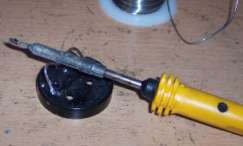 Soldering, fluxes, solders and how to work with a soldering iron? What soldering iron to use, what are the fluxes and solders? And, a little about what a soldering station is ...
Not a single serious repair is complete without soldering work. There is a soldering iron in almost every house, and soldering is now a common thing not only for technicians, but also for any homemade amateur craftsman. Without high-quality soldering, the normal operation of an electronic device (at least a contact on a chandelier, at least a capacitor on a motherboard) sooner or later, with a high probability, will be disrupted. Since during soldering, the solder and the part of the metal to which it is applied are mutually dissolved, after cooling, a rather strong joint is obtained that has good electrical conductivity. But in order for the connection to turn out to be really high-quality and durable, you have to take into account some nuances ...
The main difference between soldering irons is power. For repair of printed circuit boards and installation of small elements sensitive to static voltage, soldering irons with a power of 24-40 watts are used. For soldering wide conductors, power buses and various massive elements - 40-80 watts. Soldering irons of 100 watts or more are mainly used for soldering massive steel structures, especially non-ferrous metals with high thermal conductivity.
Do not forget about the supply voltage ...
A multimeter for dummies: the basic principles of measuring with a multimeter
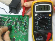 The article is dedicated to all beginners and just those for whom the principles of measuring the electrical characteristics of various components are still a mystery ...
On sale, you can find two main types of multimeters: analog and digital.
In an analog multimeter, the measurement results are observed by the movement of the arrow (like on a clock) on a measuring scale on which the values are written: voltage, current, resistance. On many (especially Asian manufacturers) multimeters, the scale is not very conveniently implemented and for someone who first took such a device in his hand, measurement can cause some problems. The popularity of analog multimeters is explained by their availability and price ($ 2-3), and the main drawback is some error in the measurement results. For more accurate tuning in analog multimeters, there is a special tuning resistor, manipulating which you can achieve a little more accuracy. However, in cases where more accurate measurements are desired, the use of a digital multimeter is best.
The main difference from analog is that the measurement results are displayed on a special screen (in older models using LEDs, in new ones on a liquid crystal display). In addition, digital multimeters have higher accuracy and are easy to use, since you do not have to understand all the intricacies of graduation of the measuring scale, as in arrow versions. A little more about what is responsible for ..
About electrical protection devices for "dummies": residual current device (RCD)
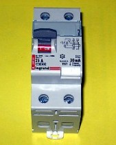 Imagine the following - a washing machine is installed in your bathroom. Whatever the well-known brand, devices of any manufacturer are subject to breakdown, and, say, the most banal thing happens - the insulation on the power cord is damaged and the network potential appears on the machine body. And this is not even a breakdown, the car continues to work, but it is already becoming a source of increased danger. After all, if we touch both the car body and the water pipe at the same time, we will close the electric circuit through ourselves. And in most cases it will be fatal.
To avoid these terrible consequences, RCDs were invented - protective shutdown devices.
An UZO is a high-speed protective switch that responds to differential current in conductors that supply electricity to the protected electrical installation - this is the "official" definition. In a more understandable language, the device will disconnect the consumer from the mains supply if a current leakage occurs to the PE (ground) conductor. Let's consider the principle of operation of the RCD ...
About electrical protection devices for dummies: circuit breakers
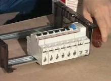 Many people remember Soviet circuit breakers - plugs. Instead of ordinary ceramic plugs, they were screwed into the shield of an electric meter. It was a compromise solution, which, in general, paid off. Indeed, thanks to this, plugs became "reusable", and without changing the existing design of the electrical panel. In general, the inventor of automatic protection devices is ABB, which patented a small-sized circuit breaker in 1923. Much time has passed since then, but the principle of operation of the circuit breaker has remained unchanged - the restoration of its normal operation with one movement of the hand.
A circuit breaker is an electrical switching device designed to conduct current in normal conditions and to automatically turn off electrical installations when short-circuit currents and overloads occur.The most common and popular today are circuit breakers that are mounted on a 35 mm DIN rail in a distribution panel.
The main parameter of circuit breakers is the rated current. This is a current whose value in a particular circuit is considered normal, i.e. for which electrical equipment is designed. For electrical installations in residential buildings, the rated current ...
