Categories: Novice electricians, Programmable controllers
Number of views: 8010
Comments on the article: 4
An example of upgrading the electrical circuit of a freight elevator using a programmable controller (PLC)
Recently, the topic of automation of various technological processes using programmable controllers (PLCs) has become increasingly popular. Despite this, there are very few practical articles on the Internet with real examples of how to program these PLCs. This topic is very interesting, because it is at the junction of electrical equipment, electronics and programming. Learning how to write PLC programs is possible without even having them. The emulation mode, which is available in all modern software packages, helps a lot with this.
In this article I will show an example of translating an electrical circuit built on relay devices (starters, relays) into a program that will work on the controller. I must say right away that this is just a small educational project and does not pretend to explain anything more than just explaining the basic principles of PLC programming with a concrete example.
Freight Relay Relay
The initial scheme for this project is a relatively simple scheme of a freight elevator (freight elevator) with lever control over two floors. The diagram is shown in the figure below.

Municipal electric hoist hoist with one engine at two stops
There is only one engine in the circuit, which raises and lowers the lift between two floors. This is a reversible three-phase asynchronous motor with a 380 V phase rotor. Starting resistors and contacts of three electromagnetic starters are connected to the engine rotor, allowing the engine to be started in 3 stages. This solution allows in the process of starting the engine to reduce its starting current and increase the starting torque.
The engine start is automated using three acceleration relays (1RU - 3RU). These are conventional 24 volt DC timers. For their power there is a step-down transformer and rectifier.
A three-phase block electromagnetic brake is connected to the motor terminals, which, when voltage is applied to the motor, brakes its shaft, and when the voltage disappears, the motor shaft is instantly clamped and fixed in a fixed position.
Engine reverse using contacts of two electromagnetic starters (in diagram B and H). Power to the circuit is supplied through a circuit breaker (on the circuit - WU) and a circuit breaker (1A).
Inclusion in work of the elevator is possible only in the presence of tension. It is controlled by a voltage relay (PH), which is located on the left side of the circuit. There are also sockets and a bell that can be turned on from any site to call the conductor.
The doors of the shaft and cab open and close manually. The elevator is controlled using the lever switch to three positions - "Up", "Down" and "Zero".
When the handle is moved to one of the extreme positions, the elevator begins to move and when the desired floor is reached, the handle is mechanically moved to the "Zero" position. In this case, the contacts in the switch circuit are broken, the starter coil is de-energized, the engine is disconnected from the network, the contacts in the circuit of its rotor open and the elevator stops. After that, you can start the movement of the elevator in the opposite direction.

The freight elevator belongs to high-risk devices and in its circuit (as in the schemes of any elevators) there are a large number of different interlocks limit switch contacts and contacts of various protective devices.
In this scheme, these are trip (end) switches that control the closing of the cabin doors, shafts on the lower and upper floors, the raising and lowering of the cabin above the working upper and lower zones, the contacts of the "slack of the hoisting ropes" that open when the cable is weakened or loosened elevator cabin, contacts of the speed limiter, catcher and cable tensioner. In total - 14 discrete sensors.
When any of the listed contacts opens, the elevator motor must instantly turn off and brake, therefore all sensors, the voltage relay contact and the “General stop” button are connected in series to the coil circuit of the electromagnetic actuators controlling the engine.
Creating a PLC program for a freight elevator
The task was that without changing anything in the device, in principle, the operation and controls of the elevator, transfer its circuit from an outdated relay view to an option using a programmable controller.
The advantage of the program form for controlling the installation is that in the future, if desired, the program can be easily modified, improve the convenience of controlling the lift, change the logic of its operation, and improve its functionality. But these actions must be accompanied by a change in the design of the lift and the addition of other additional devices to the circuit. In our version, such a task was not posed.
In this case, an option has been proposed to modernize the electrical equipment of a freight elevator by changing its control scheme with such an approach that, for example, absolutely nothing would change for a person operating such a mechanism.
Therefore, we will save the main control device for the lift - the lever switch and leave the asynchronous motor with the phase rotor with its three-stage start-up, although we still want to replace it with an asynchronous motor with a squirrel-cage rotor, which is switched on via the soft starter. But for now, we will not do this, since this solution will greatly simplify the electrical circuit of the elevator, which is not very complicated.
So, we will divide our scheme into four zones (see the elevator scheme in the figure).
")
In zone 1, we will not touch anything, because she is responsible for the sound call of the elevator and control the presence of voltage in the circuit. Zone 2 with the motor, electromagnetic brake and power contacts of the starters also does not change. All devices from zone 4 can be deleted, because the order of inclusion of contacts in the rotor circuit of the engine when it starts will be controlled by software timers. Remains zone 3. The main modernization will affect this particular zone.

As the controller, we take the PLC company Aries. The program for him will be in the language Cfc. In my opinion, this is the most convenient language for beginners. He is very similar into the language of functional blocks Fbdbut with its own little features. So many love another great language - ladder language LD. I have nothing against, but on Cfc It’s more convenient for me to compile a program for PLC, so I used this language, but here everything is for everyone. To compile the program we use package CoDeSys 2.3.

A program is a set of functional blocks (AND, OR, NOT, triggers and timers). The work program of the freight elevator in the language Cfc:

Initially we will need blocks AND (element And). At the output of the element is a logical unit (in the program -"TRUE") only when logical units are also on all inputs. If the state of even one input differs from unity, then the output is reset to zero (in the program - "False").
This element will help us organize all the interlocking contacts and safety contacts (discrete inputs), and as you remember, there are 14 of them (in the program they are indicated under the name SQ1 - SQ14). To the input of the block AND we also connect the contact of the voltage relay and the button "General stop" (SB1). For convenience, I made all the contacts on 3 elements AND, and then used another to combine them into one chain.
By default, when adding to the program, any functional unit has 2 inputs. If you need to add an additional input, you need to point at the block with the mouse, press the right button on it and select "Block input". Thus, you can add any required number of additional inputs to the block.

The lever switch is connected to two controller inputs (in the program - "SA_verh" and "SA_niz"). A switch in each of its two extreme positions supplies a logical unit to one of the two RS triggers ("RS_verh" or "RS_niz"). A trigger is an analogue of a starter coil with a blocking contact in a relay control circuit.
In order to enable it, submit the logical unit to the contact "SET"to disable - on"RESET". Trigger output "Q1"transmits a signal to one of the controller outputs -"KM1" or "KM2"to which are connected solenoid coils. Starters switch contacts and control the motor.

The three-stage start in the program is organized using 2 timers "TON". When applying a logical unit to the timer input "IN"he counts the time given at the input"PT"and switches the time delay output"Q"from logical zero to one. After the first timer (T1) is triggered by a signal from its output (Q), the time starts counting on the second timer (T2) and after a time specified at the PT input, the second timer also sends a logical unit to its output (Q) .
To controller outputs (in the program - KM3, KM4 and KM5) 3 coils of electromagnetic starter are connected. The first of them turns on immediately when you turn on KM1 or KM2 and connects the maximum resistance to the rotor of the motor, KM4 and KM5 turn on by timer and alternately short-circuit part of the starting resistance. After starting the engine, all three starters remain in the on position.

Element OR (logical OR) needed in order to simultaneously start one of the two main starters, the part of the circuit responsible for the three-stage engine start-up was included in the work. If there is a logical unit at one of the inputs of the element "OR", a logical unit is transmitted to its output, that is, for its operation, a signal at any of its inputs is enough.

Between timers and controller outputs AND with one of the inverse inputs (input circle). For this element, a logical unit at the output appears only when a logical unit signal is applied to a normal input, and a logic zero is applied to an inverse one.

The same element, only with two inverse inputs is located next to the inputs "SA_verh" and "SA_niz", receiving signals from the lever switch. This is necessary in order to ensure that all starters on the outputs are switched off when the switch returns to the zero position, when both the Up and Down circuits are open.
If there are two logical zeros at the input of such an element AND gives a logical unit at the output of the element. This signal comes through the program to the input of triggers "RESET", the triggers are reset to zero and the starters on the outputs are disabled. Elements AND with one inverse input between timers and outputs KM3 and KM4 disconnect these outputs and, accordingly, disconnect the starters responsible for shunting the resistances in the rotor circuit when the engine is stopped.

To set an inverse input or output, you need to move the mouse to the functional block, select the desired input or output, press the right mouse button and select "Invert". Similarly, any inverse input or output can be converted to normal.
Items AND Numbers 5 and 10 do not allow starters responsible for driving the "Up" and "Down" motors to turn on at the same time (protection against short circuit in the power contacts of the starters while turning them on). Although in this scheme with a lever switch, this is not possible.But since blocking contacts of this type were present in the original relay circuit, it was decided to keep them in the program for the PLC.
And finally, it remains to provide instant shutdown of the electric motor when opening any of the contacts at the input. The presence of triggers in the circuit did not allow this to be done initially. In order for the circuit to work correctly in any emergency (triggering of safety contacts, contacts of the trip switches, voltage relay contact or the “General stop” button), a circuit was added two chains of elements NOT and OR (4 and 7).
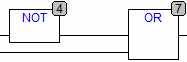
The NOT element precedes the logical unit at the input to the logical zero at the output and vice versa - the zero at the input to the unit at the output. Can you explain how the chains from NOT and OR work in the program? Write in the comments.
CFC program emulation in CoDeSys
After creating the program, you can check it in CoDeSys in emulation mode. To do this, select "Emulation Mode" in the "Online" tab, click the "Connect" button, then set the logical unit to all inputs - "TRUE", write these values to the program by clicking"Ctrl" + F7 and click F5 to start.
Emulation mode inCoDeSys:

Simulating input switching ("TRUE"and"False") you can look at the change of circuits in blue (signal path) and the change in the state of the outputs. After each change in the input state, do not forget to write these values to the program by pressing"Ctrl" + F7. To disable the emulation mode, click "Stop", then "Disconnect" on the "Online" tab and uncheck the "Emulation mode".
Conclusion
Once again, I want to note that this project was exclusively related to educational goals and has not yet been tested on a real programmable controller. If you have any questions and any of the above is not clear, ask in the comments, I will try to answer them. And it’s also very important for me to get an answer to the question - should I continue to write articles on this topic? In general, I am ready to listen to any constructive comments and suggestions.
See also at bgv.electricianexp.com
: