Categories: Featured Articles » Novice electricians
Number of views: 46734
Comments on the article: 2
Asynchronous micromotors
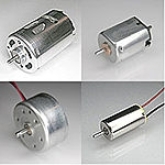 Typically, electric motors are divided into three groups: large, medium and low power. For low-power engines (we will call them micromotors), the upper limit of the power is not set, usually a few hundred watts. Micromotors are widely used in household appliances and devices (now every family has several micromotors - in refrigerators, vacuum cleaners, tape recorders, players, etc.), measuring equipment, automatic control systems, aviation and space technology, and other areas of human activity.
The first DC motors appeared in the 30s of the XIX century. A big step in the development of electric motors was made as a result of the invention in 1856 by the German engineer Siemens of a two-arm transducer and the discovery of the dynamoelectric principle in 1866. In 1883, Tesla, and in 1885, Ferrari independently invented an asynchronous AC motor. In 1884, Siemens created a commutator motor with alternating current with a series excitation winding. In 1887, Hazelwander and Dolivo-Dobrovolsky proposed a squirrel cage type rotor design, which greatly simplified the design of the engine. In 1890, Chitin and Leblanc first used a phase-shifting capacitor.
In household electrical appliances, electric motors began to be used from 1887 in fans, from 1889 in sewing machines, from 1895 in drills, and from 1901 in vacuum cleaners. However, to date, the need for micromotors has turned out to be so great (up to six micromotors are used in a modern video camera) that specialized firms and enterprises for their development and production have arisen.
Single-phase asynchronous micromotors are the most common type, they satisfy the requirements of most electric drives of devices and apparatuses, characterized by low cost and noise level, high reliability, do not require maintenance and do not contain moving contacts.
Turning on. An asynchronous micromotor can be with one, two or three windings. A single-winding motor does not have an initial starting torque, and to start it you need to use, for example, a starting motor. In a two-winding motor, one of the windings, called the main one, is directly connected to the mains supply (Fig. 1). To create a starting moment in another auxiliary winding, a current must be displaced in phase relative to the current in the main winding. For this, an additional resistor is included in series with the auxiliary winding, which can be active, inductive or capacitive in nature.
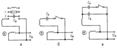
Most often, a capacitor is included in the auxiliary winding power circuit, while obtaining the optimal phase angle of the currents in the windings equal to 90 ° (Fig. 1.6). A capacitor that is constantly included in the power circuit of the auxiliary winding is called a working one. If at starting the engine it is necessary to provide an increased starting torque, then in parallel with the working capacitor S, the starting capacitor Ca is switched on for the start time (Fig. 1, c). After the engine accelerates to a speed of rotation, the starting capacitor is switched off using a relay or a centrifugal switch. In practice, they often use the version of Fig. 1.6.
The phase shift effect can be obtained by artificially increasing the active resistance of the auxiliary winding. This is achieved either by turning on an additional resistor, or by manufacturing an auxiliary winding from a high-resistance wire. Due to the increased heating of the auxiliary winding, the latter is turned off after starting the engine.Such motors are cheaper and more reliable than capacitor ones, although they do not provide a phase shift of the winding currents of 90 °.
To reverse the direction of rotation of the motor shaft, the auxiliary winding should be included in the power circuit inductor or inductor, as a result of which the current in the main winding will outstrip the current in the auxiliary winding. In practice, this method is rarely used, since the phase shift is insignificant due to the inductive nature of the resistance of the auxiliary winding.
Most often, a phase shift method is used between the main and auxiliary windings, which consists in closing the auxiliary winding. The main winding has a magnetic connection with the auxiliary, so that when the main winding is connected to the mains supply, the EMF is induced in the auxiliary and a current arises that lags behind the current of the main winding. The motor rotor begins to rotate in the direction from the main to the auxiliary winding.
Three-winding three-phase asynchronous motor can be used in single-phase power mode. Fig. 2 shows the inclusion of a three-winding motor according to the "star" and "triangle" schemes in single-phase operation (Steinmets scheme). Two of the three windings are directly connected to the supply network, and the third is connected to the supply voltage through the starting capacitor. To create the necessary starting torque, a resistor must be connected in series with the capacitor, the resistance of which depends on the parameters of the motor windings.
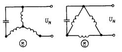
Figure 2
Windings. Unlike three-winding asynchronous motors, which are characterized by a symmetrical spatial arrangement and the same parameters of the windings on the stator, in motors with single-phase power supply, the main and auxiliary windings have different parameters. For symmetrical windings, the number of grooves per pole and phase can be determined from the expression: q = N / 2pm, where N is the number of stator grooves; m is the number of windings (phases); p is the number of poles. In asymmetrical windings, the number of grooves occupied by each winding changes significantly. Therefore, the main and auxiliary windings have a different number of turns. A typical example is the 2 / 3-1 / 3 winding (Fig. 3), in which 2/3 of the stator slots are occupied by the main and 1/3 are the auxiliary winding.
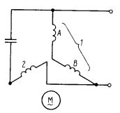
Figure 3
Design. Fig. 4 shows a cross section of a motor with two concentrated or coil windings located at the poles of the stator. Each winding (main 1 and auxiliary 2) is formed by two coils located at opposite poles. The coils are put on the poles and inserted into the yoke of the machine, which in this case has a square shape. From the side of the working air gap, the coils are held by special protrusions acting as pole shoes 3. Thanks to them, the distribution curve of the magnetic field induction in the working air gap approaches a sinusoid. Without these protrusions, the shape of the specified curve is nearly rectangular. As a phase-shifting element for such an engine, you can use both a capacitor and a resistor. You can also short-circuit the auxiliary winding. In this case, the motor is converted to an asynchronous machine with split poles.
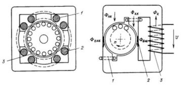
Figures 4, 5
Split pole motors are most commonly used due to their structural simplicity, high reliability and low cost. Such an engine also has two windings on the stator (Fig. 5). The main winding 3 is made in the form of a coil and is connected directly to the supply network. Auxiliary winding 1 is short-circuited and contains from one to three turns per pole. It covers part of the pole, which explains the name of the engine. The auxiliary winding is made of copper wire of round or flat shape with a cross section of several square millimeters, which bends into turns of the corresponding shape. Then the ends of the windings are connected by welding.The rotor of the engine is made short-circuited, and cooling fins are mounted at its ends, which improve heat dissipation from the stator windings.
Design options for split pole motors are shown in Figs. 6 and 7. In principle, the main winding can be located symmetrically or asymmetrically with respect to the rotor. Fig. 6 shows the design of the motor with an asymmetric main winding 5 (1 - mounting hole; 2 - magnetic shunt; 3 - short-circuited winding; 4 - mounting and alignment holes; 6 - winding frame; 7 - yoke). Such an engine has a significant scattering of the magnetic flux in the external magnetic circuit, therefore, its efficiency does not exceed 10-15%, and it is manufactured for a power of not more than 5-10 watts.
From the point of view of manufacturability, a motor with a symmetrically located main winding is more complex. In engines with a power of 10-50 W, a composite stator is used (Fig. 7, where: 1 - yoke ring; 2 - short-circuited ring; 3 - pole; 4 - squirrel cage rotor; 5 - magnetic shunt). Due to the fact that the motor poles are covered by the yoke and the windings are located inside the magnetic system, the magnetic fluxes of scattering are much less than in the design in Fig. 6. Engine efficiency 15-25%.
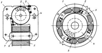
Figures 6, 7
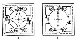
Figure 8
To change the engine speed with split poles, use a cross-pole circuit (Fig. 8). In it, it is quite simple to switch the number of pairs of poles of the stator winding, for changing which it is enough to turn on the included windings according to the included windings. In motors with split poles, the principle of speed control is also used, which consists in switching the winding coils from series to parallel.
Pryadko A. D.
Read also:Minato's magnetic motor: is there a cornucopia of magnetic energy?
See also at bgv.electricianexp.com
:
