Categories: Featured Articles » Novice electricians
Number of views: 26504
Comments on the article: 0
Types and designs of thermal relays, calculation and selection of thermal relays for motor protection
The thermal relay performs the function of protecting against prolonged overloads, their operation is similar to the operation of the thermal disconnector in circuit breakers. Depending on the magnitude of the overload (deviation from the nominal mode - I / Iн), it is triggered after an appropriate period of time, which can be calculated from the time-current characteristic of the thermal relay. Let's take a closer look at what a thermal relay is and how to choose it correctly.
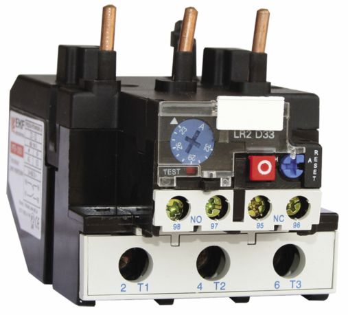
Purpose and principle of operation
When the motors are overloaded, the current consumption increases, and its heating increases accordingly. If the engine overheats, the integrity of the insulation of the windings is violated, the bearings wear out faster, they can jam. Wherein thermal release of the machine may not protect equipment. To do this, you need a thermal relay.
Overloads can occur due to phase imbalance, obstructed movement of the rotor, due to both increased mechanical load and problems with the bearings, when the motor shaft and actuators are completely jammed.
The thermal relay responds to increased current, and depending on its size it will break the power circuit after some time, thereby preserving the motor windings intact. After the subsequent elimination of the malfunction, provided the stator is in good condition, the engine can continue to work.
If the relay worked for unknown reasons, and the inspection showed that everything is in order, you can return the relay contacts to their original state, for this there is a button on it.
The relay can also work in the event of a prolonged start of the electric motor. At the same time, increased currents flow in the windings. A protracted start is a process when the engine takes a long time to reach its rated speed. May occur due to overload on the shaft, or due to low voltage in the supply network.
The time after which the relay will operate is determined by the time-current characteristics of a particular relay, in general it looks like this:
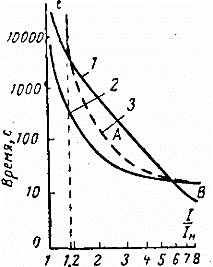
The vertical axis shows the time in seconds after which the contacts break the circuit, and the horizontal axis shows how many times the actual current exceeds the rated current. Here we see that with the rated current of the relay, the operating time of the relay tends to infinity, with an overload of 1.2 times it will open in about 5000 seconds, with an overload of 2 times - in 500 seconds, with an overload of 5-8 times the relay will work in 10 seconds.
This protection eliminates permanent engine shutdowns during short-term overloads and jerks, but saves the equipment when it goes beyond the permissible limits for a long time.
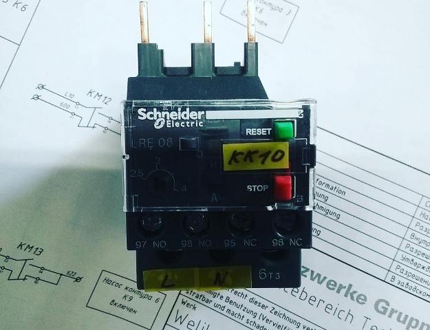
Principle of operation
The relay has a pair of bimetallic plates with different temperature expansion coefficients. The plates are rigidly connected to each other; if they are heated, the structure will bend towards the section with a lower temperature coefficient of expansion.
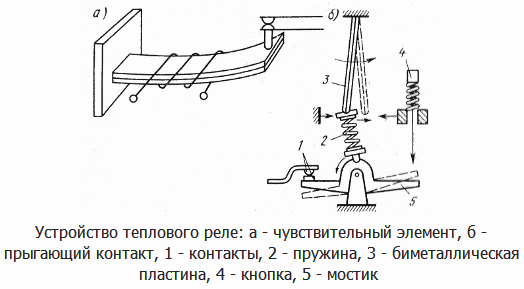
The plates are heated due to the flow of the load current or from the heater through which the load current passes, the diagram shows several turns around the bimetal. The flowing current heats the plate to a certain limit. The higher the current, the faster the heating.
It should be borne in mind that if the relay is in a hot room - you need to set the operating current with a large margin, because there is additional heating from the environment. In addition, if the relay has just worked, the contacts need some time to cool. Otherwise, a false positive may occur.
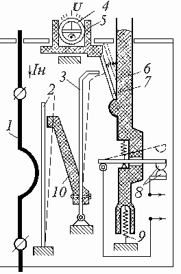
Let's look at a specific example. Above you see the TRN relay device. It is biphasic.It consists of three cells, in the extreme heating elements, in the middle there is a temperature compensator, an operating current regulator, a trip, an opening contact, a return lever.
When current flows through the heating element (1), its temperature rises, when the current reaches the set overload current, the bimetal plate (2) is deformed. The pusher (10) moves to the right and pushes the plate of the temperature compensator (3). When the overload current is reached, it bends to the right and disengages the latch (7). The release bar (6) rises and the contacts (8) open.
Types of Thermal Relays
Thermal relays can be connected to all three phases or two of three, depending on the design. Most relays are designed to meet specific magnetic starters, this is for convenience and accuracy of installation. Let's consider some of them.
RTL - suitable for use with PML starters. With a set of terminals, the KRL is used as a standalone protection device.
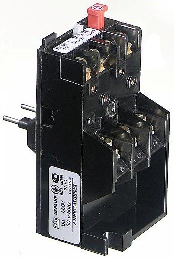
PTT - suitable for installation with PME and PMA starters. It can also be used as an independent if it is mounted on a special panel.
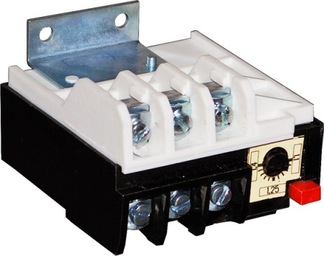
RTI - thermal relays for starters KMI and KMT. On the front you can see a couple of additional block contacts, for the implementation of display schemes and other things.
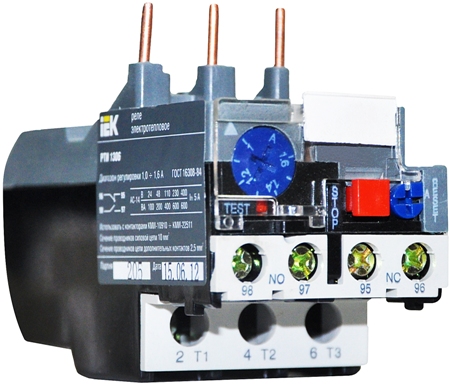
TRN is a two-phase thermal relay. It is installed in three-phase motors, at the same time it is connected to the gap of two phases. Ambient temperature does not affect its operation. On the current regulator there are 10 divisions 5 for decrease, 5 for increase, the price of one division is 5%.
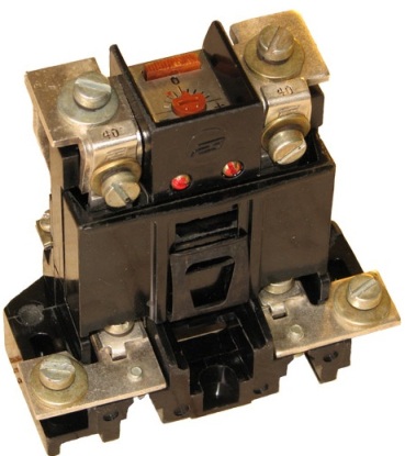
In fact, there are a great many thermal relays, but they all perform one function.
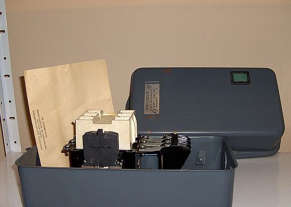
Relays are often mounted in a special iron box. In the photo, the PMA starter is the 4th value at 63 Amperes, with a three-phase thermal relay.
A thermal relay is connected to modern starters as shown in the photo below, a whole design is obtained.
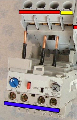
The red “test” button is needed for a test trip of the relay, and to check the possibility of opening contacts.
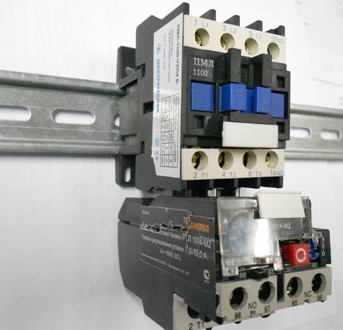
This connection method saves space on din rail.
Wiring diagram
As already mentioned, thermal relay protects against long-term overload electrical equipment. It is mounted between the power source and the consumer.
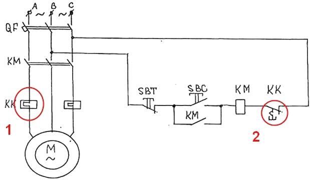
The controlled current flows through the heating elements (1), they bend open the contacts (2) of the thermal relay, in this circuit a 2-phase thermal relay is used. Its contacts open the circuit of the coil of the contactor or magnetic starter, just as if you had pressed the STOP button. When assembled, this diagram looks like this:
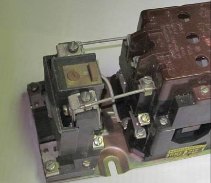
In the foreground you can see how two extreme phases are connected from the output contacts of the starter. In the background, it is seen that a terminal from the TRH contacts is connected to the relay coil.
If you use a reverse circuit of magnetic starters, then the connection is almost the same, below it is clearly shown. Contacts marked "10" and "12" are connected to the gap of the coils of the starters KM1 and KM2.
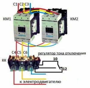
Here you can see that there is a normally closed pair and a normally open contact. This is necessary, for example, to indicate the operation of thermal protection, i.e. You can connect an indicator lamp to it or send a signal to the dispatching console or ACS.
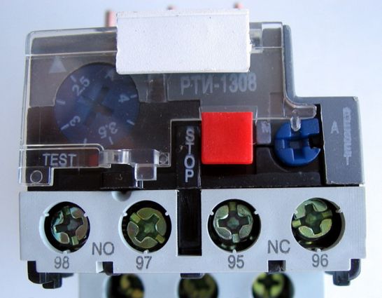
On the RTI relay, these contacts are located on the front panel:
-
NO - normally open - for indication;
-
NC - normally closed - to the starter.
The STOP button forcibly switches contacts. When activated, such a relay should cool and it will turn on again. Although in a specific example, both manual and automatic re-activation are possible. To do this, use the blue button with a cross-shaped slot on the right side of the front panel, with the lid closed, it is locked.
The choice for a specific engine
Let's say we have an AIR71V4U2 engine. Its power is 0.75 kW. We have a three-phase network with a linear voltage of 380V. The engine is designed for 220V, if you connect the windings with a triangle and 380V if a star.The rated current of such an engine with windings connected according to the star circuit 1.94A. Full information contained on his nameplatewhich you see in the photo below.
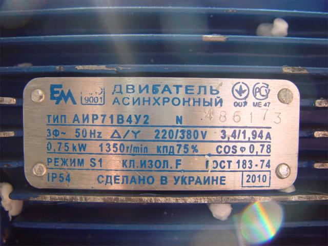
It follows that we need to choose a thermal relay for the engine with a current of 1.94 A. The response current of the thermal relay should exceed the rated current of the motor by 1.2 - 1.3 times. I.e:
Irel = IN * 1.2 ... 1.3
Let the engine work as part of a mechanism in which short-term but significant overloads are allowed, for example, for lifting small loads. Then the set current is selected 1.3 times greater than the rated current of the induction motor.
Irel = 1.94 * 1.3 = 2.522
That is, the relay should work at a current of 2.5-2.6A. Such relays are suitable for us:
-
RTL-1007, with a current range of 1.5-2.6 A;
-
RTL-1008, current range 2.4-4 A;
-
RTI-1307, current range 1.6 ... 2.5 A;
-
RTI-1308, current range 2.5 ... 4 A;
-
TRN-25 3.2A (using the regulator, you can lower or increase the current by 25%).
Relay Adjustment Methods
Step one is to determine the thermal relay setting:
N1 = (In - In) / cI
where In is the rated current of the electric motor load, In is the nominal current of the heating element of the thermal relay, and s is the scale division factor (for example, c = 0.05).
Step Two - Correction for the ambient temperature:
N2 = (T - 30) / 10
where T is the ambient temperature, ° C.
Step Three:
N = N1 + N2
Fourth step - set the regulator to the desired number of divisions N.
A temperature correction is entered if the ambient temperature is too high or low. If the temperature in the room where the relay is installed is significantly affected by the temperature in the street, then the correction should be made in winter and summer.
Check
Consider an example of a TRN type relay. To make sure that the relay is working:
1. Check the condition of the case for cracks or chips.
2. Check with connected load with rated current.
3. Disassemble the relay and check the integrity of the contacts, the absence of soot on them,
4. Check if the heaters are bent.
5. Check the distance between the bimetal and the heating elements. It should be the same, if not, then adjust with the fixing screws.
6. Supply the rated current through one of the heaters, set the setpoint to 1.5 times the rated current. In this state, the relay operates for 145 s, then the adjustment eccentric is gradually turned to the “-5” position until the relay is activated.
7. After active cooling for 15 minutes, check the second heating element in the same way.
Scheme of the test bench:
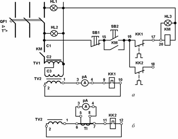
Brief Summary
Thermal relays are an important element in the protection of electrical equipment. With it, you protect your device from overloads, and its characteristics will allow you to transfer short-term current surges without false positives, which can not provide a circuit breaker.
Relays can be used both together with magnetic starters, connecting directly with its output terminals, thereby forming a single design, and as independent protective devices, located in a panel on a din rail and in control cabinets.
See also at bgv.electricianexp.com
:
