Categories: Featured Articles » Novice electricians
Number of views: 80 100
Comments on the article: 2
How to learn to read electronic circuits
For beginners, electronics engineers, it is important to understand how the parts work, how they are drawn on the circuit and how to understand the circuit diagram. To do this, you first need to familiarize yourself with the principle of operation of the elements, and how to read electronics circuits I will describe in this article on examples of popular devices for beginners.
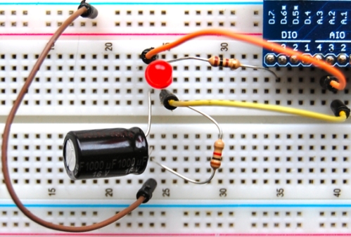
LED table lamp and flashlight circuit
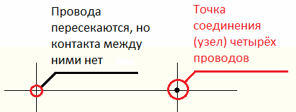
A diagram is a diagram in which, with the help of certain symbols, the details of a diagram are depicted, lines are their connections. Moreover, if the lines intersect, then there is no contact between these conductors, and if there is a point at the intersection, this is the junction of several conductors.
In addition to the icons and lines, the diagram depicts letter symbols. All designations are standardized, each country has its own standards, for example, in Russia they adhere to the standard GOST 2.710-81.
We begin the study with the simplest - the scheme of a table lamp.
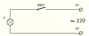
Schemes do not always read from left to right and from top to bottom, it is better to go from the power source. What we can learn from the circuit, look at its right side. ~ - means AC power.
It says “220” next to it - with a voltage of 220 V. X1 and X2 - it is supposed to be connected to the outlet using a plug. SW1 - this is how the key, toggle switch or button is depicted in the open state. L is a conditional image of an incandescent bulb.
Brief conclusions:
The diagram shows a device that connects to a 220 V AC network using a plug in an outlet or other plug connections. It is possible to turn off using a switch or button. Needed to power an incandescent lamp.
At first glance it seems obvious, but a specialist should be able to draw such conclusions by looking at the diagram without explanation, this ability will make it possible to make a diagnosis of a malfunction and fix it or assemble devices from scratch.
Let's move on to the next scheme. This is a flashlight with battery power, installed as a radiator in it Light-emitting diode.
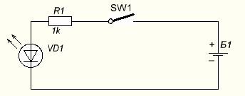
Take a look at the diagram, perhaps you will see new images for yourself. The power source is shown on the right, this is how the battery or battery looks, the long output is plus another name - Cathode, short - minus or Anode. At the LED, a plus is connected to the anode (the triangular part of the designation), and minus to the cathode (on the UGO looks like a strip).
It must be remembered that for power supplies and consumers, the names of the electrodes are vice versa. Two arrows emanating from the LED let you know that this device emits light, if the arrows pointed to it on the contrary, it would be a photodetector. Diodes have the letter designation VDx, where x is the serial number.
Important:
The numbering of parts on the diagrams goes in columns from top to bottom, from left to right.
Resistor is resistance. Converts electric current to heat, preventing its movement, looks like a rectangle, usually on the diagrams it has the letter designation "R".
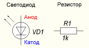
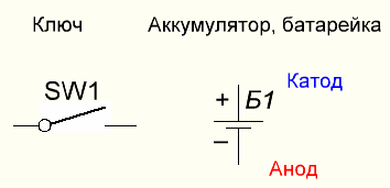
How to read electronic circuits: increasing the level of complexity
When you have already figured out the basic set of elements, it is time to familiarize yourself with more complex circuits, let's look at the transformer power supply circuit.

The main means of the converter on the circuit is the TV1 transformer, this is a new element for you. I propose to consider a number of such products.
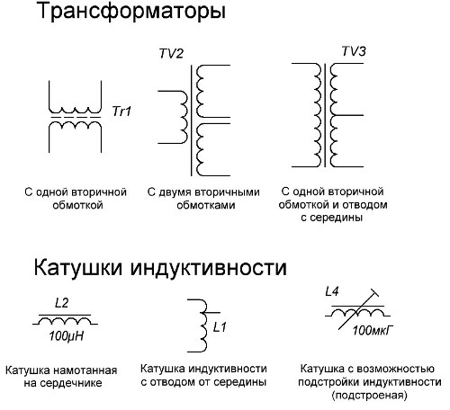
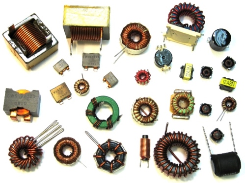
Transformers are used everywhere, either in the network (50 Hz) or in the pulse (tens of kHz) performance. Inductors are used in generators, radio transmitting devices, frequency filters, smoothing and stabilizing devices. She looks as follows.
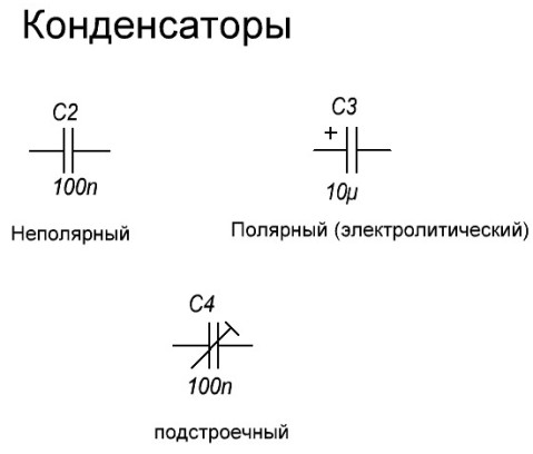
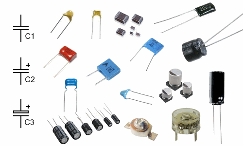
The second unfamiliar element in the circuit is a capacitor, here it is used to smooth out the ripples of the rectified voltage.In general, its main function is to accumulate energy as a charge on its plates. Depicted as follows.
In the center of the diagram is depicted bridge diode rectifier.
If we add a stabilization unit built to the circuit according to the parametric stabilizer circuit, the voltage of the power supply will be stabilized. Moreover, only from an increase in the supply voltage, with subsidence lower than the U stabilization, the voltage will be pulsating to the beat with the subsidence. VD1 is a zener diode, they are turned on in reverse bias (by cathode to a point with positive potential). They differ in the value of stabilization current (Istab) and stabilization voltage (Ustab).

Brief summary:
What can we understand from this diagram? That the power supply consists of a transformer, a rectifier and a smoothing filter on the capacitor. It is connected by the primary side (input) to an alternating current network with a voltage of 220 volts. At its output it has two detachable connections - "+" and "-" and a voltage of 12 V, unstabilized.
Let's move on to even more complex circuits and get acquainted with other elements of electrical circuits.
How to read circuits with transistors?
Transistors - these are managed keys, you can close them and open, and if you need to open it, not completely. These properties allow them to be used in both key and linear modes, which allows them to be used in a huge range of circuit solutions.
Let's look at a popular scheme among beginners - a symmetric multivibrator. This is essentially a generator that generates symmetrical pulses at its outputs. It can be used as a basis for simple flashing lights, as a frequency source for a tweeter, as a generator for a pulse converter and in many other circuits.
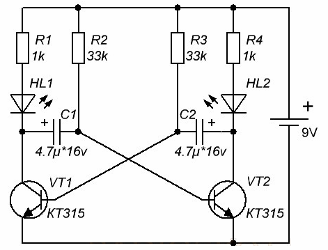
Let's go through the familiar details from top to bottom. At the top we see 4 resistors, the middle two are time-setting, and the extreme ones set the resistor current, also affect the nature of the output pulses.
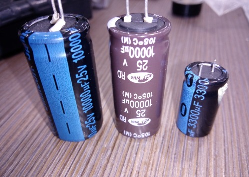
Further, HL are LEDs, and below two electrolytes are polar capacitors, when you mount them, stay careful - improper connection of the electrolytic capacitor is fraught with failure of it up to an explosion with the release of heat.
Interesting:
On the graphic designation electrolytic capacitor the “positive” capacitor lining is always marked, and on real elements - most often there is a marking of the negative leg, do not mix it up!
VT1-VT2 - these are new elements for you, this means reverse bipolar transistors (NPN), the transistor model “KT315” is indicated below. They usually have 3 legs:
1. Base.
2. The emitter.
3. The collector.
Moreover, their purpose is not indicated on the case. To determine the purpose of the conclusions, you need to use one of the search queries:
1. "Name of the element" - pinout.
2. "Name of the element" - pinout.
3. “Item Name” datsheet.
This is true for both radio tubes and modern microcircuits. Queries have almost the same meaning. That's the way I found the wiring of the KT315 transistor.
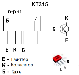
On the pinout image, it should be clearly visible: from which side to count the legs, where is the key, cut or mark so that you can correctly determine the desired output.
Interesting:
For bipolar transistors, the arrow on the emitter indicates the direction of current flow (from plus to minus), if the arrow from the base is a reverse conductivity transistor (NPN), and if to the base, then direct conductivity (PNP), often you can replace all NPN transistors with PNP , as in the multivibrator circuit, then it will be necessary to change the polarity of the power supply (plus and minus in places) because, again, the arrow on the emitter indicates the direction of current flow.
In the above diagram, the positive contact of the power source is connected to the top of the circuit, and the negative to the bottom. So on the transistor the arrow points super-down - in the direction of the current flow!
In elements with a large number of legs it matters where to connect, as well as in diodes and LEDs, if you mix the legs - in the best case the circuit will not work, and in the worst - kill the details.
What we could find out by reading the multivibrator circuit:
In this circuit, transistors and electrolytic capacitors are used, it is powered by a voltage of 9 V (although it can be more and less, for example 12 V will not damage the circuit, like 5 V).
It became clear about the method of connecting parts and turning on transistors. And also that the circuit is a device that works on the principle of an oscillator based on the process of recharging transistors, which is caused by the alternate opening and closing of each transistor in turn, when the first is open, the second is closed.
By tracing the current path (from plus to minus) and using knowledge of how does a bipolar transistor work we draw conclusions about the nature of the work.
Thyristors - semi-controlled keys, learning to read circuits
Let's look at a circuit with an equally important and common element - thyristor. I chose the word “semi-controlled” because, unlike a transistor, you can only open it, the current in it will be interrupted either when the power is interrupted or when the polarity of the voltage applied to it is changed. Opens by applying voltage to the control electrode.
Triacs - contain two thyristors connected counter-parallel. Thus, alternating current can be switched by one component, when the upper part of the (positive) half-wave of the sine wave passes, provided that there is a signal on the control electrode, one of the internal thyristors will open. When the half-wave changes its sign to negative, it will close and the second thyristor will come into operation.
Dinistors are a type of thyristor, without a control electrode, and they open, like zener diodes, to overcome a certain voltage level. Often used in switching power supplies, as a threshold element for starting self-oscillators and in devices for regulating voltage.
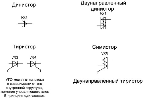
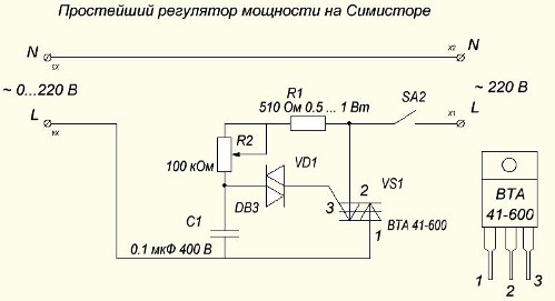
So, actually it looks on the diagram.
We carefully look at the connection. The circuit is designed to connect to an alternating current network, for example 220 V, into the gap of one of the supply wires, for example phase (L). The triac VS1 is the main power element of the circuit, its pinout from the datasheet is given at the bottom right, the 3rd output is the control. A control signal is applied to it through a bi-directional dinistor VD1 of the DB3 model designed for an on-voltage of about 30 volts.
Since all semiconductor devices in this particular circuit are bi-directional, the adjustment is made on both half-waves of a sine wave. The dinistor opens when the potential (voltage) appears on the capacitor C1, and its charge rate, therefore, the moment of opening the keys, is set by the RC circuit, consisting of R1, a variable resistor (potentiometer) R2 and C1.
This simple circuit is of great importance and application.
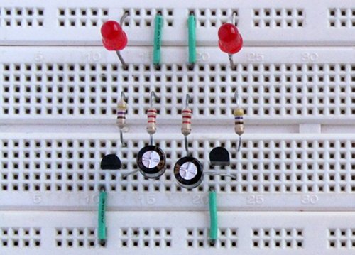
conclusions
Thanks to the ability to read electrical schematic diagrams, you can determine:
1. What does this device do, what is it for.
2. During repair - the rating of the failed part.
3. How to power this device, what kind of voltage and type of current.
4. The approximate power of the electronic device, based on the ratings of the components of the power circuits.
It is important not only to know the graphic symbols of the elements, but also the principle of their work. The fact is that these or other details may not always be used in their usual role. But within the framework of today's article it is quite difficult to consider all the common elements, since it will take a very large amount.
See also the website: Arduino Beginner's Guide - Connecting, Programming, and Managing
See also at bgv.electricianexp.com
:

