Categories: Featured Articles » Novice electricians
Number of views: 29794
Comments on the article: 1
How to calculate cable voltage loss
The issue of the quality of transmission and receipt of electrical energy largely depends on the state of the equipment that is involved in this complex technological process. Since huge power is transported over long distances in the energy sector, increased demands are placed on the characteristics of power lines.
Moreover, attention is paid to the reduction of voltage losses not only on long high-voltage mains, but also in secondary circuits, for example, voltage measuring transformers, as shown in the photograph.
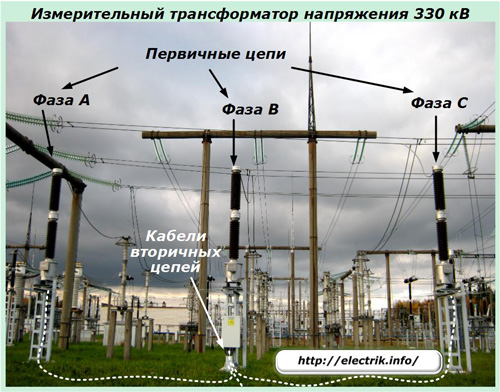
The cables of the secondary circuits of the VT from each phase are collected in one place - the terminal assembly cabinet. From this switchgear, located on the middle mast of the equipment, the voltage circuits are fed by a separate cable to the terminal block of the panel located in the relay room.
Power primary equipment is located at a considerable distance from the protections and measuring devices mounted on panels. The length of such a cable reaches 300 ÷ 400 meters. Such distances lead to noticeable voltage losses in the internal circuit, which can seriously underestimate the metrological characteristics of measuring instruments and the system as a whole.
For this reason, the quality of conversion of a primary voltage value, for example, 330 kV to a secondary value of 100 volts with the required accuracy class of 0.2 or 0.5, may not fit into the acceptable limits required for reliable operation of measuring complexes and protections.
In order to eliminate such errors during the operation phase, all measuring cables are designed for voltage losses even during the design of the electrical equipment circuit.
How voltage losses are created
The cable consists of conductive cores, each of which is surrounded by a dielectric layer. The whole structure is placed in a sealed dielectric casing.
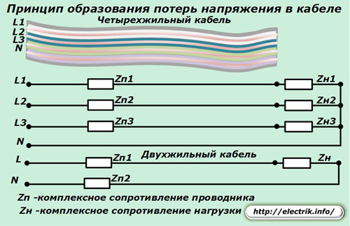
Metal conductors are located quite close to each other, tightly pressed by the protective sheath. With a long length of the highway, they begin to work like a capacitor with charge plates. Due to its action, capacitance is formed, which is an integral part of reactive.
As a result of transformations on the windings of transformers, reactors and other elements with inductances, the power of electrical energy acquires an inductive character. The resistive resistance of the core metal forms the active component of the total or complex resistance Zп of each phase.
To operate under voltage, the cable is connected to the load with a full complex resistance Zн in each core.
During cable operation in a three-phase circuit at a nominal load mode, the currents in phases L1 ÷ L3 are symmetrical, and an unbalance current very close to zero flows in the neutral wire N.
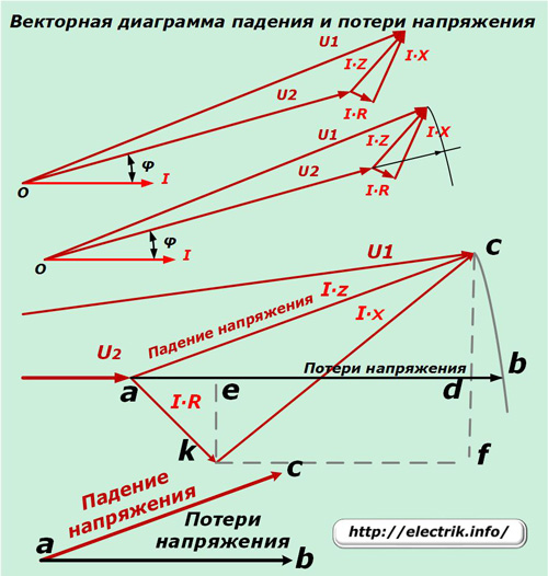
The complex resistance of the conductors when current flows through them causes a drop and voltage loss in the cable, reduces its input value, and due to the reactive component it also deflects in angle. All this is shown schematically in a vector diagram.
The voltage U2 acts at the cable output, which is deviated from the current vector by an angle φ and reduced by the value of the drop I ∙ z from the input value U1. In other words, the voltage drop vector in the cable is formed by the passage of current through the complex resistance of the conductor and is equal to the value of the geometric difference of the input and output vectors.
For clarity, it is shown on an enlarged scale and is indicated by the segment ac or the hypotenuse of the rectangular triangle ack. Its legs ak and kc denote the voltage drop across the active and reactive component of the cable resistance.
We mentally continue the direction of the vector U2 to the intersection with the circle line formed by the vector U1 from the center at point O. We have the vector ab, with an angle repeating the direction of U2 and a length equal to the arithmetic difference of the quantities U1-U2. This scalar quantity is called voltage loss.
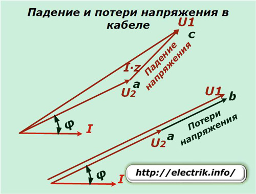
It is calculated during the creation of the project and measured during the operation of the cable to monitor the safety of its technical characteristics.
The principle of measuring voltage losses in the cable
For the experiment, it is necessary to perform two measurements with a voltmeter at different ends: the input and the load. Since the difference between them will be small, it is necessary to use a high-precision device, preferably of class 0.2.
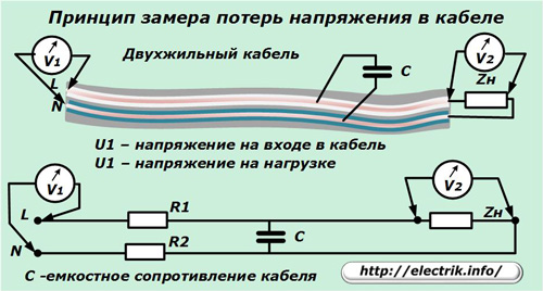
The cable length can be large, which will require considerable time for the transition from one place to another. During this period, the voltage in the network can change for various reasons, which will distort the final result. Therefore, it is customary to carry out such measurements on both sides at the same time, involve an assistant with communication equipment and a second measuring high-precision device.
Since voltmeters measure the effective value of voltage, the difference in their readings will indicate the amount of loss formed by arithmetic subtraction of the vector modules at the input and output of the cable.
As an example, we consider the voltage transformer circuits shown in the upper photos. Suppose that the linear value at the input of the cable is measured to the nearest tenth and equal to 100.0 volts, and at the output terminals connected to the load, it was 99.5 volts. This means that voltage losses are defined as 100.0-99.5 = 0.5 V. When converted to percentages, they amounted to 0.5%.
The principle of calculating voltage losses
Let us return to the vector diagram of the drop and voltage loss vectors. When the cable design is known, its resistivity is calculated from the resistivity, thickness and length of the metal of the current-carrying core.
The specific reactance and length determine the total reactance of the cable. Often, for calculation, it is quite enough to take a directory with tables and according to the brand of cable with certain technical characteristics calculate both types of resistances (active and reactive).
Knowing the two legs of a right-angled triangle, the hypotenuse is calculated - the value of the complex resistance.
A cable is created to transmit a nominal current. Multiplying its numerical value by the complex resistance, we find out the magnitude of the voltage drop - side ac. Both legs are computed similarly: ak (I ∙ R) and kс (I ∙ X).
Next, simple trigonometric calculations are performed. In the triangle ake, the leg ae is defined by multiplying I ∙ R by cos φ, and in Δ сkf the length of the side cf (I ∙ X is multiplied by sin φ). Please note that the segment cf is equal to the length of the segment ed, as the opposite side of the rectangle.
Add the obtained lengths ae and ed. We find out the length of the segment ad, which is slightly less than ab or voltage loss. Due to the small value of bd, this value is easier to neglect than to try to take it into account in the calculations, which is almost always done.
This simple algorithm is the basis for calculating a two-core cable when it is supplied with an alternating sinusoidal current. The technique works with minor adjustments for DC circuits.
In three-phase lines operating on three- or four-wire cables, a similar calculation procedure is used for each phase. Due to this, it is much more complicated.

How the calculation is carried out in practice
The times when such calculations were carried out manually by formulas have long passed. Design organizations have long used special tables, graphs, and diagrams summarized in technical manuals. They eliminate the routine work of performing numerous mathematical operations and the associated operator errors.
As an example, we can cite the techniques set forth in publicly accessible directories:
-
Fedorov's electricity supply in 1986;
-
on design work for power supply of power lines and electric networks edited by Bolshman, Krupovich and Samover.
With the massive introduction of computers in our lives, programs for calculating voltage losses began to be developed, which greatly facilitated this process. They are created both for performing complex calculations of power supply networks by design organizations, and for an approximate assessment of the preliminary results of using a separate cable.
Owners of electrical sites for these purposes place various calculators on their resources that allow you to quickly assess the capabilities of cables of different brands. To find them it is enough in Google search to enter the corresponding query and select one of the services.
As an example, consider the operation of a calculator of this kind.
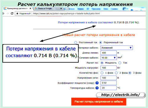
We will do a test test for him and enter the initial data in the appropriate fields:
-
alternating current;
-
aluminum;
-
line length - 400 m;
-
cable section - 16 mm square (most likely it is not a cable, but one core);
-
power calculation - 100 W;
-
number of phases - 3;
-
network voltage - 100 volts;
-
power factor — 0.92;
-
temperature is 20 degrees.
We press the button “Calculation of voltage losses in the cable” and look at the result of the service.
The result was quite plausible: 0.714 volts or 0.714%.
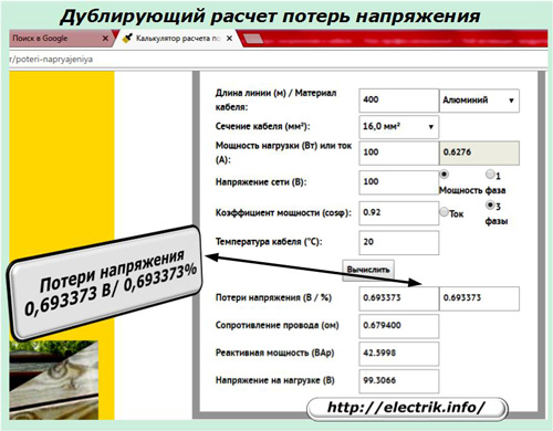
Let's try to double-check it on another site. To do this, go to a competing service and enter the same values.
As a result, we get a quick calculation.
Now you can compare the results performed by different services. 0.714-0.699373 = 0.021 volts.
The accuracy of the calculation in both cases is quite acceptable not only for quick analysis of cable performance, but also for other purposes.
A method of comparing the work of two online services showed their efficiency and the absence of data entry errors that a person can commit by inattention.
However, having performed such a calculation, it is too early to calm down. It is necessary to conclude that the selected cable is suitable for operation under specific operating conditions. For this, there are technical requirements for permissible voltage deviations from the norm.
Normative documents on the deviation of voltage from the nominal value
Depending on their nationality, use one of the following.
TKP 45-4.04—149—2009 (RB)
The document is valid in the territory of the Republic of Belarus. When receiving the result, pay attention to clause 9.23.
SP 31-110-2003 (RF)
Current standards are provided for use at power supply facilities of the Russian Federation. Consider clause 7.23.
GOST 13109
Replaced on January 1, 1999, the interstate standard, GOST 13109 from 1987. Analyze according to paragraph 5.3.2.
Ways to reduce cable loss
When the calculation of voltage losses in the cable is made and the result is compared with the requirements of regulatory documents, we can conclude that the cable is suitable for work.
If the result showed that the errors are overestimated, then you must choose another cable or specify the conditions for its operation. In practice, a typical case is often encountered when already working cable revealed by measuring methods that voltage losses in it exceed permissible norms. Due to this, the quality of power supply facilities is reduced.
In such a situation, it is necessary to take additional technical measures to reduce the material costs required for a complete cable replacement due to:
1. restrictions on leaking load;
2. increasing the cross-sectional area of the conductive conductors;
3. reduce the working cable length;
4. lower operating temperature.
The effect of cable power on voltage loss
The flow of current through a conductor is always accompanied by the release of heat in it, and heating affects its conductivity.When increased power is transmitted through the cable, they, creating a high temperature, increase voltage losses.
To sometimes reduce them, it is quite enough for some consumers who receive electricity via cable to simply turn off and restart on another bypass chain.
This method is acceptable for branched circuits with a large number of consumers and redundant lines for their connection.
The increase in the cross-sectional area of the cable core
This method is often used to reduce losses in the circuits of voltage measuring transformers. If you connect another cable to a working cable and connect their cores in parallel, the currents will split and reduce the load in each wire. Voltage losses are also reduced, and the accuracy of the measuring system is restored.
Using this method, it is important not to forget to make changes to the executive documentation and especially the installation diagrams used by the repair and maintenance personnel to conduct periodic maintenance. This will prevent workers from making mistakes.
Reduced cable length
The method is not typical, but in some cases it can be used. The fact is that cable routing schemes at many developed energy enterprises are constantly being developed and improved in relation to the delivered equipment.
Due to this, opportunities are created to shift the cable with a reduction in its length, which will reduce the resulting voltage loss.
Influence of ambient temperature
Cable operation in rooms with increased heating leads to a violation of the heat balance, an increase in the errors of its technical characteristics. Laying along other highways or using a thermal insulation layer can reduce voltage losses.
As a rule, it is possible to effectively improve cable characteristics in one or more ways with their complex application. Therefore, when such a need arises, it is important to consider all possible solutions to the problem and choose the most suitable option for local conditions.
It should be borne in mind that the competent management of the electric economy requires constant analysis of the operational situation, anticipation of the development of events, and the ability to calculate various situations. These qualities distinguish a good electrician from the general mass of ordinary workers.
See also at bgv.electricianexp.com
:


