Categories: Novice electricians, Industrial electrician
Number of views: 14968
Comments on the article: 4
What determines the long-term permissible cable current
What determines the long-term permissible cable current? To answer this question, we will have to consider transient thermal processes that occur under conditions when an electric current flows through the conductor. Heating and cooling a conductor, its temperature, connection with resistance and cross-section - all this will be the subject of this article.
Transition process
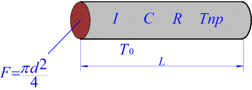
To begin with, consider a conventional cylindrical conductor of length L, diameter d, cross-sectional area F, resistance R, volume V, obviously equal to F * L, through which current I flows, the specific heat of the metal of which the conductor is made - C, the mass of the conductor is equal to
m = V * Ω,
where Ω is the density of the metal of the conductor, S = pi * d * L is the area of the side wall through which cooling occurs, Tpr is the current temperature of the conductor, T0 is the ambient temperature, and, accordingly, T = Tpr - T0 is the temperature change. KTP is the heat transfer coefficient, numerically characterizing the amount of heat transferred from a unit surface of a conductor in 1 second at a temperature difference of 1 degree.
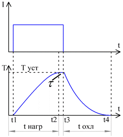
The figure shows graphs of the current and temperature in the conductor over time. From time t1 to time t3, current I flowed through the conductor.
Here you can see how, after turning on the current, the temperature of the conductor gradually rises, and at time t2 it ceases to increase, stabilizes. But after turning off the current at time t3, the temperature begins to gradually decrease, and at time t4 it again becomes equal to the initial value (T0).
So, it is possible to write down the heat balance equation, a differential equation for the heating process of the conductor, where it will be reflected that the heat released on the conductor is partially absorbed by the conductor itself, and partially is given to the environment. Here is the equation:

On the left side of equation (1) is the amount of heat released in the conductor during the time dt, the passage of current I.
The first term on the right side of equation (2) is the amount of heat absorbed by the conductor material, from which the conductor temperature increased by dT degrees.
The second term in the right-hand side of equation (3) is the amount of heat that was transferred from the conductor to the environment during the time dt, and it is related to the surface area of the conductor S and the temperature difference T through the thermal conductivity coefficient Ktp.
First, when the current is turned on, all the heat released in the conductor is used to heat the conductor directly, which leads to an increase in its temperature, and this is due to the heat capacity C of the conductor material.
With increasing temperature, the temperature difference T between the conductor itself and the environment increases accordingly, and the heat generated partially goes already to increase the ambient temperature.
When the temperature of the conductor reaches a steady stable value of Tust, at this moment all the heat released from the surface of the conductor is transferred to the environment, so the temperature of the conductor no longer increases.
The solution to the differential heat balance equation will be:
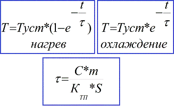
In practice, this transient process lasts no more than three time constants (3 * τ), and after this time the temperature reaches 0.95 * Tust. When the heating transition process stops, the heat balance equation is simplified, and the steady-state temperature can be easily expressed:

Permissible current
Now we can come to the exact value of the current that appears to be a long-term allowable current for a conductor or cable. Obviously, for each conductor or cable there is a certain normal continuous temperature, according to its documentation.This is such a temperature at which a cable or wire can be continuously and for a long time without harm to itself and to others.
From the above equation it becomes clear that a specific current value is associated with such a temperature. This current is called permissible cable current. This is such a current, which, when passing through the conductor for a long time (more than three time constants), heats it to an allowable, that is, normal temperature Tdd.

Here: Idd - long-term allowable conductor current; TDD - permissible conductor temperature.
To solve practical problems, it is most convenient to determine the long-term allowable current according to special tables from the PUE.
In the event of a short circuit, a significant short circuit current flows through the conductor, which can significantly heat the conductor, exceeding its normal temperature. For this reason, conductors are characterized by a minimum cross-section based on the condition of short-term heating of the conductor by a short circuit current:

Here: Ik - short circuit current in amperes; tp is the reduced short-circuit current duration in seconds; C is a coefficient that depends on the material and construction of the conductor, and on the short-term allowable temperature.
Section Connection
Now let's see how the long-term allowable current depends on the cross section of the conductor. Having expressed the area of the side wall through the diameter of the conductor (the formula at the beginning of the article), assuming that the resistance is related to the cross-sectional area and the specific resistance of the material of the conductor, and substituting the well-known formula for resistance into the formula for Idd, given above, we obtain for a long-term allowable current Idd formula :
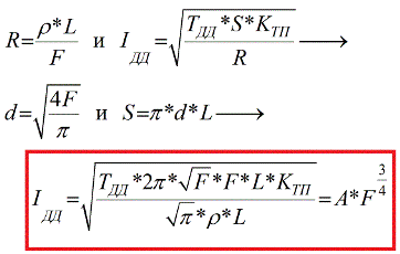
It is easy to see that the connection between the long-term admissible current of the conductor Idd and the cross-section F is not directly proportional, here the cross-sectional area is raised to the power ¾, which means that the long-term permissible current increases more slowly than the cross-section of the conductor. Other constants, such as resistivity, heat transfer coefficient, permissible temperature, are individual by definition for each conductor.
In fact, it is, the dependence cannot be direct, because the larger the cross section of the conductor, the worse the cooling conditions of the inner layers of the conductor, the more acceptable temperature is reached at a lower current density.
If you use conductors of larger cross section to avoid overheating, this will lead to an excessive consumption of material. It is much more profitable to use several conductors of small cross section laid in parallel, that is, use multicore conductors or cables. And the relationship between the long-term allowable current and the cross-sectional area as a whole turns out like this:
Current and temperature
To calculate the temperature of a conductor with a known current and specified external conditions, consider the steady state when the temperature of the conductor reaches Tust and no longer increases. Initial data - current I, heat transfer coefficient Ktp, resistance R, side wall area S, ambient temperature T0:

A similar calculation for continuous current:

Here, T0 is taken as the calculated ambient temperature, for example + 15 ° C for laying under water and in the ground, or + 25 ° C for laying in the open air. The results of such calculations are given in tables of continuous currents, and for air they take a temperature of + 25 ° C, because this is the average temperature of the hottest month.
Dividing the first equation by the second, and expressing the temperature of the conductor, we can obtain a formula for finding the temperature of the conductor at a current other than the long-term allowable, and at a given ambient temperature, if a long-term allowable current and a long-term allowable temperature are known, and you do not need to resort to using other constants:

From this formula it is seen that the temperature rise is proportional to the square of the current, and if the current increases by 2 times, then the temperature increase will increase by 4 times.
If external conditions differ from the design
Depending on the actual external conditions, which may differ from the calculated ones depending on the method of laying, for example, several conductors (cable) located in parallel or laying in the ground at a different temperature, an adjustment of the maximum permissible current is required.
Then, the correction factor Kt is introduced, by which the long-term allowable current is multiplied under known (tabular) conditions. If the external temperature is lower than the calculated one, then the coefficient is greater than one; if it is higher than the calculated one, then, accordingly, Kt is less than one.
When laying several parallel conductors very close to each other, they will additionally heat each other, but only if the surrounding environment is stationary. Actual conditions often lead to the fact that the environment is mobile (air, water), and convection leads to cooling of the conductors.
If the medium is almost stationary, for example, when laying in a pipe underground or in a duct, then mutual heating will cause a decrease in the long-term allowable current, and here you need to enter the correction factor Kn again, which is given in the documentation for cables and wires.
See also at bgv.electricianexp.com
:
