Categories: Featured Articles » Practical Electronics
Number of views: 44174
Comments on the article: 0
Transformers for UMZCH
 One of the most popular amateur radio designs are sound power amplifiers UMZCH. For high-quality listening to music programs at home, most often they use fairly powerful, 25 ... 50W / channel, usually stereo amplifiers.
Such a large power is not needed at all in order to get a very high volume: an amplifier working at half the power allows for a cleaner sound, distortions in this mode, and even the best UMZCH has them, they are almost invisible.
It is quite difficult to assemble and set up a good powerful UMZCH, but this statement is true if the amplifier is assembled from discrete parts - transistors, resistors, capacitors, diodes, maybe even operational amplifiers. Such a design can be done by a sufficiently qualified radio amateur, who has already assembled more than one or two amplifiers, burning on the first experiments not one kilogram of powerful output transistors.
Modern circuitry avoids such material, and most importantly, moral costs. To assemble a sufficiently powerful and high-quality UMZCH, you can buy one or two microcircuits, add a few passive parts to them, solder all this on a small printed circuit board, and please, before you UMZCH, which will work immediately after switching on.
The playback quality will be very good. Of course, it will not be possible to get a “tube” sound, but many proprietary, and, especially, Chinese amplifiers, will be left behind. A vivid example of such a solution to the problem of high-quality sound can be considered the chip TDA7294.
The bipolar supply voltage of the microcircuit has a very large range of ± 10 ... ± 40V, which makes it possible to obtain power from the microcircuit in excess of 50W at a load of 4Ω. If such power is not required, simply lower the supply voltage a little. The output stage of the amplifier is made on field-effect transistors, which ensures good sound quality.
It is very difficult to disable a chip. The output stage has protection against short circuit, in addition there is also thermal protection. The chip, as an amplifier, operates in class AB, the efficiency of which is 66%. Therefore, in order to obtain an output power of 50 W, a power supply with a power of 50 / 0.66 = 75.757 W will be required.
The assembled amplifier is mounted on the radiator. To reduce the dimensions of the radiator, it’s not bad at all that the heat from the radiator is removed by a fan. For these purposes, a small computer cooler, for example, from video cards, is quite suitable. The design of the amplifier is shown in Figure 1.
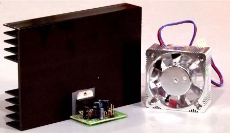
Figure 1. Amplifier on TDA7294 chip
It should be noted a small feature of the TDA7294 chip. For all such powerful microcircuits, the rear metal back with a hole for attaching to the radiator is connected to a common circuit wire. This allows you to fix the chip on the metal housing of the amplifier without an insulating strip.
On the TDA7294 chip, this fastener is electrically connected to the negative terminal of the power source, terminal 15. Therefore, an insulating gasket with heat-conducting paste KPT-8 is simply necessary. It is even better if the microcircuit is installed on the radiator without laying at all, only with heat-conducting paste, and the radiator itself is isolated from the body (common wire) of the amplifier.
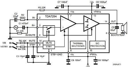
Figure 2. Typical TDA7294 switching circuit
A lot can be said about the amplifiers on the TDA7294 chip, and those few lines that were written above do not at all pretend to be complete information. This amplifier is mentioned only to show how much power a transformer might need, how to determine its parameters, because the article is called “Transformers for UMZCH”.
It often happens that the construction begins with the creation of prototypes, the power of which is produced from the laboratory power supply. If the scheme turned out to be successful, then all the rest of the “carpentry” work begins: the case is made or a suitable one from a similar industrial device is used. At the same stage, the power supply is manufactured and a suitable transformer is selected.
So what kind of transformer is needed?
It was calculated a little higher that the power supply should be at least 75 watts, and this is for only one channel. But where can you find a monophonic amplifier now? Now this is at least a two-channel device. Therefore, for the stereo option, a transformer with a power of at least one hundred and fifty watts is required. In fact this is not true.
Such a large power may be required only if a sinusoidal signal is amplified: just fed a sinusoid to the input and sit, listen. But long listening to a monotonous mournful buzz is unlikely to be a pleasure. Therefore, normal people more often listen to music or watch movies with sound. This is where the difference between the musical signal and the pure sine wave affects.
A real musical signal is not a sinusoid, but a combination of large short-term peaks and long-term signals of low power, so the average power consumed from the power source is much less.
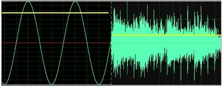
Figure 3. Actual sound power. Mid levels (yellow line) of sinusoidal and real sound signals at the same maximum levels
How to calculate the power supply UMZCH
The methodology for calculating the power supply is given in the article "Calculation of the power supply for the power amplifier", which can be found at the link,
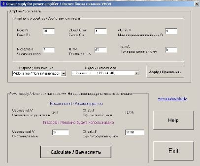
The article provides considerations on choosing the parameters of the power supply, where you can also download the program for calculating the power supply taking into account the features of reproduced music programs. The program works without installation in the system, just unzip the archive. The results of the program are saved in a text file that appears in the folder where the calculation program is located. Screenshots of the program are shown in figures 4 and 5.
Figure 4. Entering data into the calculation program
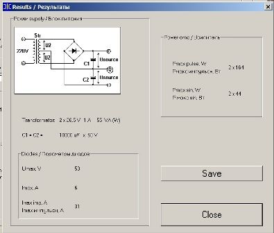
The calculations were performed for the power supply assembled according to the scheme shown in Figure 5.
Figure 5. Power supply UMZCH. Calculation results
Thus, for a 50W dual-channel amplifier with a 4Ω load, a 55W transformer is required. Secondary winding with a midpoint with voltages of 2 * 26.5V with a load current of 1A. From these considerations, you should choose a transformer for UMZCH.
It would seem that the transformer turned out to be rather weak. But, if you carefully read the article mentioned just above, then everything falls into place: the author convincingly enough tells what criteria should be taken into account when calculating the UMZCH power supply.
Here you can immediately ask a counter question: “And if the power of the transformer at hand will be greater than the calculation?”. Yes, nothing bad will happen, just the transformer will work half-heartedly, will not particularly strain and get very hot. Naturally, the transformer output voltages should be the same as those calculated.
Overall power of the transformer
It is not hard to notice that the more powerful the transformer, the larger its size and weight. And this is not at all surprising, because there is such a thing as the overall power of a transformer. In other words, the larger and heavier the transformer, the greater its power, the greater the power of the load connected to the secondary winding.
Calculation of overall power by the formula
To determine the overall power of the transformer, it is enough to measure the geometric dimensions of the core with a simple ruler, and then, with acceptable accuracy, calculate everything using a simplified formula.
P = 1.3 * Sc * So,
where P is the overall power, Sc = a * b is the core area, So = c * h is the window area. Possible types of cores are shown in Figure 5. Cores assembled according to the HL scheme are called armored, while submarine cores are called core.
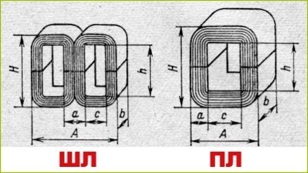
Figure 6. Types of transformer cores
In the textbooks of electrical engineering, the formula for calculating the overall power is awesome, and much longer. In the simplified formula, the following conditions are accepted that are inherent in most network transformers, just some averaged values.
It is believed that the efficiency of the transformer is 0.9, the frequency of the mains voltage is 50 Hz, the current density in the windings is 3.5 A / mm2, and the magnetic induction is 1.2 T. Furthermore, copper fill factor is 0.4, and steel fill factor is 0.9. All these values are included in the “real” formula for calculating the overall power. Like any other simplified formula, this formula can give a result with an error of fifty percent, such is the price paid for simplifying the calculation.
Here it’s enough to recall at least the efficiency of the transformer: the greater the overall power, the higher the efficiency. So transformers with a power of 10 ... 20 W have an efficiency of 0.8, and transformers 100 ... 300 W and higher have an efficiency of 0.92 ... 0.95. Within the same limits, other quantities that are part of the “real” formula can vary.
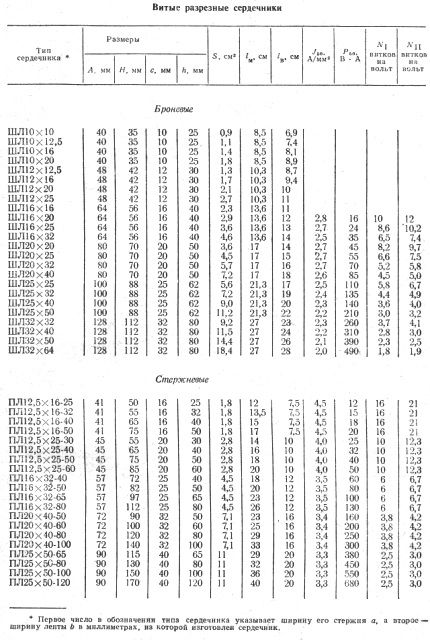
The formula, of course, is quite simple, but there are tables in the directories where "everything is already calculated for us." So do not complicate your life, and take advantage of a finished product.
Figure 7. Table for determining the overall power of the transformer. Values calculated for 50Hz
The third digit in the marking of the core of the submarine indicates the parameter h - the height of the window, as shown in Figure 6.
In addition to the overall power, the table also has such an important parameter as the number of turns per volt. Moreover, such a pattern is observed: the larger the core size, the smaller the number of turns per volt. For the primary winding, this number is indicated in the penultimate column of the table. The last column indicates the number of turns per volt for the secondary windings, which is slightly larger than in the primary winding.
This difference is due to the fact that the secondary winding is located farther from the core (core) of the transformer and is in a weakened magnetic field than the primary winding. To compensate for this weakening, it is necessary to slightly increase the number of turns of the secondary windings. Here, a certain empirical coefficient comes into effect: if at a current in the secondary winding of 0.2 ... 0.5 A the number of turns is multiplied by a factor of 1.02, then for currents of 2 ... 4 A the coefficient increases to 1.06.
How to determine the number of turns per volt
Many formulas in electrical engineering are empirical, obtained by the method of numerous experiments, as well as trial and error. One of these formulas is the formula for calculating the number of turns per volt in the primary winding of the transformer. The formula is quite simple:
ω = 44 / S
here, everything seems to be clear and simple: ω is the desired number of turns / volts, S is the core area in square centimeters, but 44 is, as some authors say, a constant coefficient.
Other authors substitute 40 or even 50 into this formula “constant coefficient”. So who is right and who is not?
To answer this question, the formula should be slightly transformed, instead of the “constant coefficient” substitute the letter, well, at least K.
ω = K / S,
Then instead of a constant coefficient, a variable is obtained, or, as programmers say, a variable. This variable can take various values, naturally, to some extent. The magnitude of this variable depends on the core design and the grade of transformer steel. Usually the variable K is in the range 35 ... 60. Smaller values of this coefficient lead to a more stringent mode of operation of the transformer, but facilitate winding due to fewer turns.
If the transformer is designed to work in high-quality audio equipment, then K is chosen as high as possible, usually 60.This will help get rid of interference with the frequency of the network coming from the power transformer.
Now you can refer to the table shown in Figure 7. There is a core ШЛ32X64 with an area of 18.4 cm2. The penultimate column of the table indicates the number of turns per volt for the primary winding. For iron, ШЛ32X64 is 1.8 turns / V. To find out what magnitude K the developers were guided in calculating this transformer, it is enough to make a simple calculation:
K = ω * S = 1.8 * 18.4 = 33.12
Such a small coefficient suggests that the quality of transformer iron is good or simply sought to save copper.
Yes, the table is good. If there is a desire, time, core and winding wire, it remains only to roll up the sleeves and wind the required transformer. It is even better if you can buy a suitable transformer or get it from your own “strategic” reserves.
Industrial Transformers
Once upon a time, Soviet industry produced a whole series of small-sized transformers: TA, TAN, TN and CCI. These abbreviations are deciphered as, anode transformer, anode-filament, filament and transformer for powering semiconductor equipment. That is the transformer of the TPP brand may be the most suitable for the amplifier considered above. Transformers of this model are available with a capacity of 1.65 ... 200W.
With a rated power of 55W, a transformer TPP-281-127 / 220-50 with a power of 72W is quite suitable. From the designation, it can be understood that this is a transformer for powering semiconductor equipment, development serial number 281, primary winding voltage 127 / 220V, mains frequency 50Hz. The last parameter is quite important, considering that the transformers of the CCI are also available at a frequency of 400 Hz.
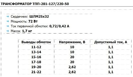
Figure 8. Transformer parameters ТПП-281-127 / 220-50
Primary current is indicated for voltages 127 / 220V. The table below shows the voltages and currents of the secondary windings, as well as the transformer leads to which these windings are soldered. The scheme of the whole variety of transformers CCI is one: all the same windings, all the same pin numbers. Here are just the voltages and currents of the windings for all models of transformers are different, which allows you to choose a transformer for any occasion.
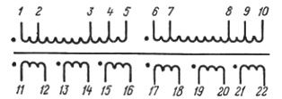
The following figure shows the electrical diagram of the transformer.
Figure 9. Electrical circuit of transformers CCI
For a power supply unit of a two-channel amplifier with a power of 50W, an example of the calculation of which was given just above, a transformer with a power of 55W is required. Secondary winding with a midpoint with voltages of 2 * 26.5V with a load current of 1A. It is quite obvious that to obtain such voltages, it will be necessary to connect the in-phase windings of 10 and 20V, and the in-phase winding of 2.62V
10 + 20-2.62 = 27.38V,
which is almost consistent with the calculation. There are two such windings, which are connected in series in one with the midpoint. The winding connection is shown in Figure 10.
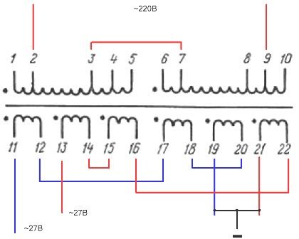
Figure 10. Connection of transformer windings ТПП-281-127 / 220-50
The primary windings are connected in accordance with the technical documentation, although you can use other taps, which will more accurately select the output voltage.
How to connect the secondary windings
Windings 11-12 and 17-18 are connected in phase - the end of the previous winding, with the beginning of the next (the beginning of the windings is indicated by a dot). The result is one winding with a voltage of 30V, and according to the conditions of the task 26.5 are required. To get closer to this value, windings 19-20 are connected to windings 11-12 and 17-18 in antiphase. This connection is shown by the blue line, one half of the winding with a midpoint is obtained. The red line shows the connection of the other half of the winding shown in Figure 5. The connection of points 19 and 21 forms the midpoint of the winding.
Series and parallel windings
With a series connection, it is best if the permissible winding currents are equal, the output current for two or more windings will be the same.If the current of one of the windings is less, it will be the output current of the resulting winding. This reasoning is good when there is a circuit diagram of a transformer: just solder the jumpers and measure what happened. And if there is no scheme? This will be discussed in the next article.
Parallel connection of the windings is also allowed. Here the requirement is this: the voltage of the windings must be the same, and the connection is in-phase. In the case of the transformer TPP-281-127 / 220-50, it is possible to connect two 10-volt windings (leads 11-12, 13-14), two 20-volt windings (leads 15-16, 17-18), two windings at 2.62V (conclusions 19-20, 21-22). Get three windings with currents 2.2A. The connection of the primary winding is made in accordance with the transformer reference data.
That's how well it turns out if the transformer data is known. One of the important parameters of the transformer is its price, which to a large extent depends on the imagination and arrogance of the seller.
Considered as an example, the transformer TPP-281-127 / 220-50 from various Internet sellers is offered at a price of 800 ... 1440 rubles! Agree that it will be more expensive than the amplifier itself. The way out of this situation can be the use of a suitable transformer obtained from old household equipment, for example, from lamp TVs or old computers.
Boris Aladyshkin
Read also on this topic:How to determine unknown transformer parameters
See also at bgv.electricianexp.com
:

