Categories: Featured Articles » Practical Electronics
Number of views: 170495
Comments on the article: 1
What practical schemes can be done on the 555 timer
 With the modern development of electronics in China, it seems that you can buy anything you want: from home theaters and computers to simple products such as electrical outlets and plugs.
Somewhere in between all kinds of time relays, flashing Christmas lights, clocks with thermometers, power regulators, temperature regulators, photorelay and much more. As the great satirist Arkady Raikin said in a monologue about the deficit: “Let everything be, but let something be missing!” In general, just what is included in the “repertoire” of simple amateur radio designs is lacking.
Despite such competition from the Chinese industry, the interest of amateur designers in these simple designs has not been lost so far. They continue to be developed and in some cases find worthy application in small home automation devices. Many of these devices were born thanks to integrated timer NE555 (domestic analogue of KR1006VI1).
These are the already mentioned photo relay, various simple alarm systems, voltage converters, PWM - regulators of DC motors and much more. Several practical constructs available for repetition at home will be described below.
555 timer photo relay
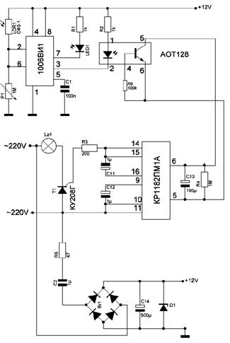
The photo relay shown in Figure 1 is designed to control lighting.
Picture 1.
The control algorithm is traditional: in the evening, when the illumination decreases, the light turns on. The lamp turns off in the morning when the illumination reaches a normal level. The circuit consists of three nodes: a light meter, a load switching unit, and a power supply. It is better to start describing the operation of the circuit backwards - in advance - the power supply unit, the load switching unit and the light meter.
Power Supply
In such designs, this is the very case when it is reasonable to apply, violating all safety recommendations, a power supply unit that does not have galvanic isolation from the network. To the question why this is possible, the answer will be as follows: after setting up the device no one will climb into it, everything will be in an insulating casing.
External adjustments are also not expected, after adjustment it remains only to close the lid and hang the finished photo relay in place, let yourself work. Of course, if there is a need, then the only “sensitivity” setting can be brought out using a long plastic tube.
There are two ways to ensure security during the setup process. Or use an isolation transformer (safety transformer) or power the device from the laboratory power supply. At the same time, the mains voltage and the bulb can not be connected, and the operation of the photocell can be controlled by the LED1.
The power supply circuit is quite simple. It represents a bridge rectifier Br1 with a quenching capacitor C2 for an alternating voltage of at least 400V. Resistor R5 is designed to smooth the inrush current through a capacitor C14 (500.0 μF * 50V) when the device is turned on, and also “in combination” is a fuse.
The Zener diode D1 is designed to stabilize the voltage at C14. As a zener diode, 1N4467 or 1N5022A is suitable. For the Br1 rectifier, diodes 1N4407 or any low-power bridge, with a reverse voltage of 400V and a rectified current of at least 500mA, are quite suitable.
Capacitor C2 should be shunted with a resistor with a resistance of about 1MΩ (not shown in the diagram) so that after turning off the device it does not “click” the current: kill, of course, will not kill, but still quite sensitive and unpleasant.
Load switching unit
Made using a specialized chip KR1182PM1A, which allows you to make many useful devices. In this case, it is used to control the KU208G triac. The best “analog” of BT139-600 gives the best results: the load current is 16A at a reverse voltage of 600V, and the current of the control electrode is much less than that of KU208G (sometimes KU208G has to be selected according to this indicator). BT139 is able to withstand pulsed overloads up to 240A, which makes it extremely reliable when working in various devices.
If BT139 is installed on a radiator, then the switched power can reach 1KW, without a radiator, load control up to 400W is permissible. In the case when the power of the bulb does not exceed 150W, you can completely do without a triac. To do this, the La1 lamp output, right according to the circuit, should be connected directly to the terminals 14, 15 of the microcircuit, and the resistor R3 and triac T1 should be excluded from the circuit.
Let's go further. The KR1182PM1A microcircuit is controlled through terminals 5 and 6: when they are closed, the lamp is off. There may be an ordinary contact switch, however, working the other way around - the switch is closed, and the lamp is off. It’s so much easier to remember this “logic."
If this contact is opened, the capacitor C13 starts to charge and, as the voltage on it increases, the brightness of the lamp glow gradually increases. For incandescent lamps, this is very important, since it increases their service life.
By choosing a resistor R4, you can adjust the degree of charge of the capacitor C13 and the brightness of the lamp. In the case of the use of energy-saving lamps, the capacitor C13 can not be set, as well as the KR1182PM1A itself. But this will be discussed below.
Now we are getting closer to the main point. Instead of a relay, just out of an effort to get rid of the contacts, the control was entrusted to the AOT128 transistor optocoupler, which can be successfully replaced with an imported “analog” 4N35, however, with such a replacement, the value of the resistor R6 should be increased to 800K ... 1MΩ, since at 4K35 the imported 4N35 does not work will be. Proven by practice!
If the optocoupler transistor is open, its K-E transition, like a contact, will close the terminals 5 and 6 of the KR1182PM1A chip and the lamp will be turned off. To open this transistor, you need to light up the optocoupler LED. In general, it turns out the opposite: the LED is off, and the lamp is on.
Light meter
Based on 555, it is very simple. To do this, it is enough to connect the LDR1 photoresistor and the tuning resistor R7 connected in series to the timer inputs, with which the threshold of the photo relay is set. The switching hysteresis (dark - light) is provided by the timer itself, it input comparators. Remember these "magic" numbers 1 / 3U and 2 / 3U?
If the photosensor is in the dark, its resistance is high, so the voltage on the resistor R7 is low, which leads to the fact that the output of the timer (pin 3) is set to high and the optocoupler LED is off and the transistor is closed. Consequently, the bulb will be turned on, as was written earlier in the subheading “Load Switching Unit”.
In the case of illumination of the photosensor, its resistance becomes small, on the order of several KOhm, so the voltage on the R7 resistor rises to 2 / 3U, and a low voltage level appears at the output of the timer, the optocoupler LED lights up, and the lamp – load goes out.
Here someone may say: “It will be difficult!”. But almost always everything can be simplified to the limit. If you plan to light energy-saving lamps, then a smooth start is not required, and you can use a conventional relay. And who said that only the lamps and only turn on?
If the relay has several contacts, then you can do whatever you want, and not only turn it on, but turn it off. Such a scheme is shown in Figure 2 and does not need special comments. The relay is selected from the conditions so that the coil current is not more than 200mA at an operating voltage of 12V.
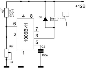
Figure 2
Preinstallation Schemes
In some cases, you need to turn on something with some delay regarding the power on of the device. For example, first apply voltage to the logic circuits, and after a while, power the output stages.
Such delays are implemented on the 555 timer quite simply. Schemes of such delays and timing diagrams of operation are shown in Figures 3 and 4. The dashed line shows the voltage of the power supply, and the solid output of the microcircuit.
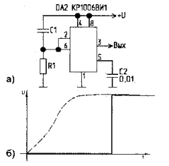
Figure 3. After turning on the power, a high level appears at the output with a delay.
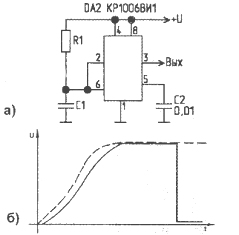
Figure 4. After turning on the power, a low level appears at the output with a delay.
Most often, such “installers” are used as components of more complex schemes.
555 Timer Alarm Devices
Liquid level switch
The circuit of the detector is self-oscillating multivibratorwhom we have long met.
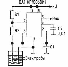
Figure 5
Two electrodes are immersed in a container with water, for example, a pool. While they are in the water, the resistance between them is small (water is a good conductor), so the capacitor C1 is shunted, the voltage across it is close to zero. Also, the zero voltage at the input of the timer (pins 2 and 6), therefore, the output (pin 3) will be set high, the generator does not work.
If for some reason the water level drops and the electrodes are in the air, the resistance between them will increase, ideally just a break, and the capacitor C1 will not be bridged. Therefore, our multivibrator will work - pulses will appear at the output.
The frequency of these pulses depends on our imagination and on the parameters of the RC circuit: it will be either a flashing light or a nasty speaker squeak. Along the way, you can turn on adding water. In order to avoid overfilling and in time to turn off the pump, it is necessary to add one more electrode and a similar circuit to the device. Here the reader can already experiment.
The simplest alarm
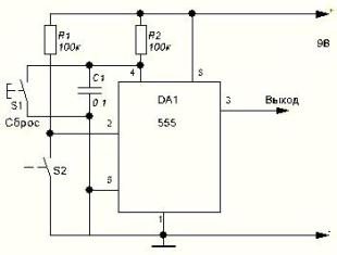
Figure 6.
When you press the limit switch S2, a high level voltage appears at the output of the timer, and remains so even if S2 is released and no longer held. The device can be brought out of this state only by pressing the “Reset” button.
While we stop at this, maybe someone will need time to take a soldering iron and try to solder the devices under consideration, explore how they work, at least experiment with the parameters of RC circuits. Listen to how the speaker beeps or the LED flashes, compare what the calculations give, whether the practical results are much different from the calculated ones.
In the next article we will consider PWM - regulators, voltage converters, as well as drivers for control transistors mosfet.
CONTINUED ARTICLE: 555 voltage converters
Boris Aladyshkin
See also at bgv.electricianexp.com
:
