Categories: Featured Articles » Practical Electronics
Number of views: 351,264
Comments on the article: 28

How to power a cordless screwdriver from an electrical network

 

How to power a cordless screwdriver from the mains?Cordless screwdriver is designed for screwing - unscrewing screws, screws, screws and bolts. It all depends on the use of interchangeable heads - bits. The scope of the screwdriver is also very wide: it is used by furniture assemblers, electricians, construction workers - finishers fasten gypsum boards with it and in general everything that can be assembled using a threaded connection.

This is a professional screwdriver application. In addition to professionals, this tool is also purchased exclusively for personal use during repair and construction work in an apartment or a country house, garage.
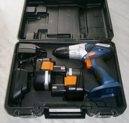
Cordless screwdriver

The cordless screwdriver is lightweight, small in size, does not require a network connection, which allows you to work with it in any conditions. But the whole trouble is that the battery capacity is small, and after 30 - 40 minutes of intensive work, you have to set battery for charging no less than 3 to 4 hours.

In addition, batteries tend to become unusable, especially when they do not use a screwdriver regularly: they hang a carpet, curtains, paintings and put it in a box. A year later, they decided to screw a plastic baseboard, and the screwdriver does not “pull”, Accumulator charging helps a little.

cordless screwdriverA new battery is expensive, and not always on sale you can immediately find exactly what you need. In both cases, there is only one way out - to power the screwdriver from the mains through the power supply. Moreover, most often the work is carried out in two steps from the power outlet. The design of such a power supply will be described below.

In general, the design is simple, does not contain scarce parts, it can be repeated by anyone who is even a little familiar with electrical circuits and knows how to hold soldering iron. If you recall how many screwdrivers are in operation, then we can assume that the design will be popular and in demand.

The power supply must satisfy several requirements at once. Firstly, it is quite reliable, and secondly small-sized and lightweight and convenient for carrying and transporting. The third requirement, perhaps the most important thing, is the falling load characteristic, which allows avoiding damage to the screwdriver during overloads. Of no less importance is the simplicity of design and the availability of parts. All these requirements are fully met by the power supply, the design of which will be discussed below.

The basis of the device is a 60-watt Feron or Toshibra electronic transformer. Such transformers are sold in electrical goods stores and are designed to power halogen lamps with a voltage of 12 V. Typically, such lamps illuminate shop windows.

In this design, the transformer itself does not require any alterations, it is used as it is: two input network wires and two output wires with a voltage of 12 V. The circuit diagram of the power supply is quite simple and is shown in Figure 1.

Schematic diagram of the power supply

Figure 1. Schematic diagram of the power supply

The transformer T1 creates a falling characteristic of the power supply due to the increased dissipation inductance, which is achieved by its design, which will be discussed above. In addition, the T1 transformer provides additional galvanic isolation from the network, which increases the overall electrical safety of the device, although this isolation is already in the electronic transformer U1 itself. By selecting the number of turns of the primary winding, it is possible, within certain limits, to control the output voltage of the unit as a whole, which allows it to be used with different types of screwdrivers.

The secondary winding of the transformer T1 is made with tap from the midpoint, which allows instead diode bridge apply a half-wave rectifier on just two diodes. Compared to the bridge circuit, the loss of such a rectifier due to the voltage drop across the diodes is two times lower. After all, there are two diodes, not four. In order to further reduce the power loss on the diodes in the rectifier, a diode assembly with Schottky diodes is used.

The low-frequency ripple of the rectified voltage smooths electrolytic capacitor C1. Electronic transformers operate at a high frequency, of the order of 40 - 50 KHz, therefore, in addition to ripples with the mains frequency, these high-frequency ripples are also present in the output voltage. Considering the fact that a half-wave rectifier increases the frequency by a factor of 2, these pulsations reach 100 or more kilohertz.

Oxide capacitors have a large internal inductance, so high-frequency pulsations cannot smooth out. Moreover, they will simply uselessly heat up the electrolytic capacitor, and may even render it unusable. To suppress these pulsations, a ceramic capacitor C2 is installed parallel to the oxide capacitor, of small capacity and with a small intrinsic inductance.

The operation indicator of the power supply can be monitored by the glow of the LED HL1, the current through which is limited by the resistor R1.

Separately, it should be said about the appointment of resistors R2 - R7. The fact is that electronic transformer Originally designed to power halogen lamps. It is assumed that these lamps are connected to the output winding of the electronic transformer even before it is connected to the network: otherwise it simply does not start without load.

If the electronic transformer is included in the network in the described design, then the subsequent pressing of the screwdriver button will not make it rotate. To prevent this from happening in the design and resistors R2 - R7 are provided. Their resistance is chosen so that the electronic transformer starts up confidently.


Parts and construction

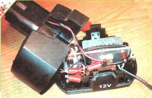
The power supply is located in the case of a regular battery that has expired, unless, of course, it has been thrown away yet. The basis of the design is an aluminum plate with a thickness of at least 3 mm, located in the middle of the battery case. The overall design is shown in Figure 2.

Power supply for cordless screwdriver

Figure 2. Power supply for a cordless screwdriver

All other parts are attached to this plate: an electronic transformer U1, a transformer T1 (on the one hand), and a diode assembly VD1 and all other parts, including the power button SB1, on the other. The plate also serves as a common output voltage wire, so the diode assembly is installed on it without laying, although for better cooling the heat sink surface of the VD1 assembly should be lubricated with heat transfer paste KPT-8.

The T1 transformer is made on a ferrite ring of size 28 * 16 * 9 from ferrite grade НМ2000. Such a ring is not deficient, widespread enough, problems with the acquisition should not arise. Before winding the transformer, first with a diamond file or just sandpaper, you should dull the outer and inner edges of the ring, and then insulate it with varnish cloth tape or FUM tape used for winding heating pipes.


As mentioned above, the transformer must have a large leakage inductance. This is achieved by the fact that the windings are located opposite each other, and not one under the other. The primary winding I contains 16 turns in two wires of the brand PEL or PEV-2. The wire diameter is 0.8 mm.

The secondary winding II is wound with a bundle of four wires, the number of turns 12, the diameter of the wire is the same as for the primary winding. To ensure the symmetry of the secondary winding, it should be wound in two wires at once, more precisely the harness. After winding, as is usually done, the beginning of one winding is connected to the end of the other. For this winding will have to "ring" the tester.

As the SB1 button, the MP3-1 microswitch is used, in which a normally closed contact is activated.A pusher is installed in the bottom of the power supply housing, which is connected to a button through a spring. The power supply is connected to a screwdriver, exactly the same as a regular battery.

If the screwdriver is now placed on a flat surface, the pusher presses the SB1 button through the spring and the power supply turns off. As soon as the screwdriver is picked up, the released button will turn on the power supply. It remains only to pull the trigger of the screwdriver and it will work.


A bit about the details

Details in the power supply are few. Capacitors it’s better to use imported ones, it’s now even easier than finding parts of domestic production. VD1 diode assembly of type SBL2040CT (rectified current 20 A, reverse voltage 40 V) can be replaced with SBL3040CT, in extreme cases, two domestic diodes KD2997. But the diodes indicated in the diagram are not a deficit, since they are used in computer power supplies, and buying them is not a problem.

The design of the transformer T1 was mentioned above. As an LED, HL1 is suitable for anyone that is at hand.

Setting up the device is simple and comes down to only unwinding the turns of the primary winding of the transformer T1 to achieve the desired output voltage. The rated supply voltage of screwdrivers, depending on the model, is 9, 12 and 19 V. Unwinding the turns from the transformer T1, it is necessary to achieve, respectively, 11, 14 and 20 V.

When writing this article, the diagram and illustrations from the journal RADIO No. 07 for 2011 were used. The article "Mains power supply for a screwdriver" K. Moroz.

See also at bgv.electricianexp.com:

  • How to make a power supply from an electronic transformer
  • How is an electronic transformer
  • The electrical circuit of the power supply for the garage
  • Simple emergency light source
  • Power supplies for electronic devices - device and principle of operation of the main ...

  •  
     
    Comments:

    # 1 wrote: | [quote]


    Quote from your text: "Secondary II is wound with a four-wire bundle ..."
    Why 4 wires? Just two.
    And does he need this trance at all, will the friction clutch handle the overload?

     
    Comments:

    # 2 wrote: Boris | [quote]


    Yes, Sergey, absolutely right, you need two wires, just each with a double harness. Just arithmetic failed. And what about the friction clutch? If you don’t particularly pull it, then it’s okay. And with large tightening torques, it is probably better to leave it. Still some kind of protection. In the next article we will talk about some more applications of the electronic transformer and its device.
    Regards, Boris.

     
    Comments:

    # 3 wrote: Victor | [quote]


    But is it possible to use the charging unit that comes with it for powering the screwdriver by carefully connecting the screwdriver and charger terminals?

     
    Comments:

    # 4 wrote: andy78 | [quote]


    Charging and discharging are different processes and it is better not to mix them. Yes, and you need to charge the screwdriver according to the instructions, observing the charging time and focusing on the signal LEDs, because This process with modern batteries is quite intelligent and serious. The article describes the option when there is no working battery, it’s a pity to buy a new one, but I want to work with a screwdriver, i.e. A variant of a simple power supply for a screwdriver with the help of which it is possible to work from a conventional electric network in the absence of batteries is proposed.

     
    Comments:

    # 5 wrote: Victor | [quote]


    So that’s exactly what I meant.
    I have a screwdriver itself, it has two dead batteries and a battery pack. Buying new batteries costs the same as buying a new screwdriver, and a new screwdriver is also reluctant to buy, so the idea was born of using a charger as a power supply to a screwdriver, and discarding the batteries.
    But, probably, this will not work, because the charger probably has a certain control unit (at least there are control lamps in it), which will “guess” that something other than the battery is connected to it.
    In any case, you can just try :-)

     
    Comments:

    # 6 wrote: Advisor | [quote]


    I use a 12 volt battery from an uninterruptible power supply from my computer, when I need to disconnect it and connect it to a screwdriver, the contacts are made from a dead battery pack, wires can be made of any length so as not to carry the battery on my neck.

     
    Comments:

    # 7 wrote: Kirill Ivanovich | [quote]


    Interesting. And actually quite ...
    Here are just a couple of questions:
    60W - is it really enough? Or is it due to size limitations? For example, from the options available to me there are 70W and 105W. Both are the same size. There is hope, cutting off the ears, fit into the case from the AB. What is fraught or disadvantageous in choosing a more powerful one?
    More ... Ring I can order this:

    Relative magnetic permeability 2000
    Material N27
    d 26.8 mm
    d2 13.5 mm
    Description R 25/10 core
    h 11 mm
    Inductance constant 2.15 µH

    In my inexperienced opinion, the closest option available. Does it fit? I see the length of the coil is slightly (18%) increasing. Is it critical?

    And let me go back to the charger again. In our situation, the sense of him is really like a goat's milk. But on the evon transformer can BP be bungled? The power of the device is 65W. Add a rectifier or use an existing one (it’s probably present), separating the excess electronics ... Although it’s not a fact that it will fit in the case from the battery ... This is probably another story ...

     
    Comments:

    # 8 wrote: | [quote]


    Is it possible to raise the output voltage T1 to 20V, the shurik according to the passport 18v. What is the output voltage drop under load?

    Applied the standard rectifier-transformer-diode bridge circuit - a bulky design is obtained. Power transformer at least 100W. Less - gets warm

     
    Comments:

    # 9 wrote: | [quote]


    Is it worth it to gut the old battery?
    I made in the back of the screwdriver (behind the engine) a socket for the power supply that came bundled soldered inside to the contacts of the battery connector. And the charger, into which this unit is inserted, can generally be ejected because the current and voltage are the same both at the input and at the output, and both bulbs always light up and do not go out on it. That is, the charger simply never stops charging.
    As a result, I got a cordless screwdriver that is always in charge during operation, and when you need to move more than 2 meters from the outlet, you just pull out the cord and work from the "warm" native battery). The main thing is not to forget to connect it to charging again.
    Features: if the battery is disconnected from the battery and from the mains while the screwdriver is operating, the speed drops significantly, which indicates a lack of power supply (and not surprisingly, it is designed for long-term charging and produces only 0.3 A). In the future I plan to solve this problem with a more powerful power supply, but while the battery is still half-dead, I do not really dare.
    TEMP screwdriver 18-volt.

     
    Comments:

    # 10 wrote: | [quote]


    I powered the shurik from the computer power supply, plus I attached an old sidyuk (with a play button) plus old computers. active speakers (more precisely, the barrel organ was planned at first, because the "hacky" died), we got a multi-media screwdriver :)

     
    Comments:

    # 11 wrote: | [quote]


    But have you forgotten that the electric equipment of the screwdriver, in addition to the engine, also includes a PWM controller with a powerful field-effect transistor? What will it be to this transistor if, due to the steeply falling characteristic of the PSU, the control voltage at its gate drops from 12V to 6..7? And if you take into account that the current is 6..10A, and the cooling is almost none? The result is easy to predict: a PWM controller transistor will operate in the ACTIVE mode with a large drawdown, with a large voltage drop in the channel, highlighting a LARGE power that CANNOT dissipate and as a result will BURN, most likely, together with the controller. So the conclusion is this: The falling characteristic is acceptable in the absence of a regular PWM controller, for example, in all kinds of wrenches and so on. For normal BW, the most rigid characteristic is necessary. In this case, there should be protection against overload by current. When jammed, it can save a slow fuse for current 10..15A.In the case of electronic transes, I would not use an additional trans (a drop in efficiency, in conditions of tightness - a big minus), but I would modify the output winding of the ET, adjusting the voltage to the maximum value (with a margin of 1..1.5 V). And further. I do not quite understand if there is a high-voltage smoothing capacitor inside the ET? If not, it MUST BE INSTALLED!, At least from the outside, 47..150uF 400V.

     
    Comments:

    # 12 wrote: Misha | [quote]


    Advisor,
    As for connecting to a computer, thank you very much, genius, I tried, it seems to work, I don’t know the truth about the reliability of such a connection, will such a coupling affect the computer’s power supply or a screwdriver?

     
    Comments:

    # 13 wrote: | [quote]


    An interesting article, useful in everyday life.

     
    Comments:

    # 14 wrote: | [quote]


    If I understand correctly, PS for a 12-volt screwdriver is described here. And what needs to be changed in order for 18 to get off? Thanks in advance.

     
    Comments:

    # 15 wrote: | [quote]


    I have an 18-volt Mastermax screwdriver, I feed it with a dead battery from an uninterruptible power supply, connecting it with 0.75 sq. Cross-section wires. 1.5 m long with crocodiles.

    All OK :)

     
    Comments:

    # 16 wrote: Boris Aladyshkin | [quote]


    Sergei, a 4-wire harness is needed in order to reduce the harmful effects of the surface effect. With a bundle of 4 wires, wind two windings at once, and then connect the beginning of one with the end of the other, that is, in accordance - in series. When soldering a bundle, try to ensure that all cores are soldered. The easiest way is a winding wire such as PEL, etc. Irrigate using aspirin: drag the wire over the tablet by warming it with a soldering iron. The method is good, but it has one drawback, a lot of very smelly smoke is emitted. The best result is provided by ordinary rosin, if the tin-coated conductor is stretched on an ordinary piece of pine board, or even birch plywood. It is not known what substances the wood emits, but the method is very effective, even better than aspirin.

    But is it possible to use the charging unit that comes with it for powering the screwdriver by carefully connecting the screwdriver and charger terminals?

    No, you can’t, because the charger gives much less current than the battery can give. It is enough to recall a car here: when the engine starts, the starter takes a current of several hundred amperes, while the battery is charged with a current of one tenth of the battery capacity, amperes five or six. Everyone knows this, but for some reason they think differently about a screwdriver.

     
    Comments:

    # 17 wrote: Andrey Alekseevich | [quote]


    The article is interesting, but I’m absolutely zero in electronics ... I just wanted to buy a power supply with the appropriate output voltage: 12 V, insert a power supply socket instead of a battery. It turned out that there are many such PSUs, but they differ in the output current strength: 2 A, 3 A, 5 A ... Can you tell me which one is correct? 12 V screwdriver

     
    Comments:

    # 18 wrote: | [quote]


    I made my secondary in a native trance instead of the standard winding, and in order to start another loop of wasps in series with a chain of a 20 Ohm resistor and a 0.22 μF capacitor. Now I closed everything, I waited half an hour - this resistor is idling :(, so I think ..., it would be better to solder the light into the load instead of bothering with the wasps.

     
    Comments:

    # 19 wrote: | [quote]


    Andrey Alekseevichfirstly, they already wrote above that it’s not directly desirable ..
    as well as recommendations began with a 60-watt power supply, i.e. 60/12 volts = 5 amps, it is necessary to take with a margin so that it does not heat up.

     
    Comments:

    # 20 wrote: power engineer | [quote]


    I used a similar power supply circuit for the Metabo screwdriver when the battery died, and the new one cost like a screwdriver .. I threw out the old battery banks and placed a traditional 60-watt transformer, a 10-amp diode bridge and filter capacitors with a total capacity of 10,000 microfarads in the case. He refused the stabilizer, given the large currents and small housing sizes.The power cord is made authentic for greater mobility during work. I work in the garage, I did not notice any significant changes in the torque. Over time, when affordable banks appeared to repair the battery, I went over the second battery, and now there are no problems with the duration of the work.

     
    Comments:

    # 21 wrote: | [quote]


    And how can I remake my cordless screwdriver on a network one with its parameters: 14.4V 1000mAh (mAh)?
    Thank you in advance!

     
    Comments:

    # 22 wrote: Vitaly Zhukov | [quote]


    Most often, screwdrivers fail batteries. Especially when working in the cold. A new set of batteries from the same company is more expensive than a new screwdriver with batteries. We are used to paying for a company label. The easiest way to do this is to: buy a cheap battery pack for a screwdriver, better looking like yours, though not branded. And rearrange the batteries from it to your unit. Most often they fit perfectly. Check polarity. And so you save on price differences. And this is ten times cheaper than the new branded battery pack! Maybe a little lose in capacity. But there is a trick: before charging, the batteries “train” or “pump” with a serious balancing charger. You can change the batteries in the service, but it’s more expensive, and they will supply you with the same cheap batteries.

    There is one radical way to increase the battery capacity of a screwdriver at times: remove the standard one, and connect any other powerful one with wires. Though automobile. And work at least all day. You can find it easier. And place it in a backpack behind your back, or hang it from a belt next to a screwdriver holster. And then the builders often hold it between the legs, which is uncomfortable and dangerous on the roofs.

     
    Comments:

    # 23 wrote: | [quote]


    Hello! Tell me, please, is the sb1 button an obligatory element, so that it does not work at idle, or is it just energy saving? So I do not want to bother with her .... Thank you in advance!

     
    Comments:

    # 24 wrote: Vitaliy | [quote]


    Why are you shoving all these PSUs into a pen? it’s easier to make them a separate unit, and connect them to the device with a wire! and the weight is less and if the screwdriver falls, the power supply unit will not suffer and 220vol will not have to be held in hands! You can work in damp rooms!

     
    Comments:

    # 25 wrote: Sergei | [quote]


    “Why are you shoving all of these PSUs into a pen? ..” Yes, everything is logical here. The screwdriver is balanced precisely with the BP (AB) in the handle. Without a battery, it is unstable and unstable on the surface. In addition, to work for a long time with a screwdriver, with a poor weight distribution, oh, how shitty. So the weight is less - this is not always good.

     
    Comments:

    # 26 wrote: | [quote]


    Very interesting article, thank you very much. An old, but very reliable AEG screwdriver, batteries died a week ago. The screwdriver has served me for 15 years, I don’t know how much I know, I used to buy Since with electronics on YOU, could you tell me a simpler version of the power supply assembly? I don’t try to build in the battery compartment, but the option from a computer uninterruptible is also not suitable.
    Battery powered screwdriver 12v; 1,4Ah
    Answer if possible by mail
    Thanks in advance, Nikolay.

     
    Comments:

    # 27 wrote: | [quote]


    Tell me, can I replace the second trance with some standard one, which you can just buy. And then somehow reluctance to buy a wire for winding a bay for 500 rubles to winding 20 turns.

     
    Comments:

    # 28 wrote: Glory | [quote]


    Very helpful article. From personal experience: I connected Makita 12v to a 300W computer PSU - protection works (15A), I had to fuse a 260W transformer, a secondary winding with a midpoint and two Schottky 40A diodes. The moment is very weak. Connecting a capacity of 10,000 microfarads equalized the moment, in sensation, to battery life. I tried to use lithium-ion: three in series - poorly pulled, four - smokes the PWM speed controller. normally they pull only 3 + 3 in parallel, but the problem is with self-discharge - you need to select the same banks.It turned out the most practical to buy nickel-cadmium cans from the same Chinese, to solder the battery. Just take it with capacity with a margin - they are still lower by half, charging remains standard.