Categories: Practical Electronics, Home automation
Number of views: 93247
Comments on the article: 8
Thermostat for electric boiler
 Description of a simple and reliable temperature regulator circuit for a heating system.
Russian winter is harsh and cold, and everyone knows about it. Therefore, the premises where people are located must be heated. The most common is central heating or individual gas boilers.
Often there are situations when neither one nor the other is available: for example, in a clean field there is a small room of a water pumping station, and there the driver is on duty around the clock. It can also be a guard tower or a separate room in a large uninhabited building. There are many such examples.
In all these cases, it is necessary to arrange heating using electricity. If the room is small, then it is quite possible to do with a conventional oil-filled electric radiator for domestic use. For a larger room with an area of about 15 - 20 square meters, water heating is most often arranged using a radiator welded from pipes, which is often called a register.
If you let things go on their own and do not monitor the temperature of the water, then sooner or later it will simply boil and the case may end in failure of everything electric boilerFirst of all, its heating element. To prevent such an unfortunate event, the heating temperature is controlled by a thermostat.
One of the possible options for such a device is proposed in this article. Of course, this winter is already running out, but we should not forget that sledges are best prepared in the summer.
Functionally, the device can be divided into several nodes: the temperature sensor itself, comparing device (comparator) and a load control device. The following is a description of the individual parts, their diagram and principle of operation.
temperature sensor
A distinctive feature of the described design is that it is used as a temperature sensor conventional bipolar transistor, which allows you to abandon the search and purchase thermistors or sensors of various types, for example TCM.
The operation of such a sensor is based on the fact that, like all semiconductor devices, the parameters of transistors to a large extent depend on the ambient temperature. First of all, this is the reverse current of the collector, which increases with increasing temperature, which affects the operation of, for example, amplification stages. Their operating point is shifted so that significant signal distortion occurs, and in the future the transistor simply ceases to respond to the input signal.
This situation is inherent mainly in circuits with a fixed base current. Therefore, transistor cascade circuits with feedback elements are used that stabilize the operation of the cascade as a whole, and also reduce the effect of temperature on the operation of the transistor.
Such a temperature dependence is observed not only for transistors, but also for diodes. To verify this, using a digital multimeter, it is enough to “ring” any diode in the forward direction. Typically, the device will show a figure close to 700. This is just a direct voltage drop on the open diode, which the device displays in millivolts. For silicon diodes at a temperature of 25 degrees Celsius, this parameter is approximately 700 mV, and for germanium diodes about 300.
If now this diode is slightly warmed up, at least with a soldering iron, then this figure will gradually decrease, therefore it is considered that the temperature coefficient of the voltage of the diodes is -2mV / deg. The minus sign in this case indicates that with increasing temperature the forward voltage on the diode will decrease.
This dependence also allows the use of diodes as temperature sensors.If the transistor transitions “ring” with the same device, the results will be very similar, therefore transistors are often used as temperature sensors.
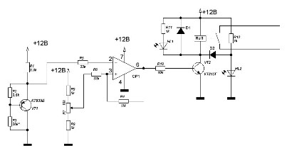
In our case, the operation of the entire temperature regulator is precisely based on this “negative” property of the cascade with a fixed base current. The temperature controller circuit is shown in Figure 1.
Figure 1. Scheme of the thermostat (clicking on the picture will open the scheme on a larger scale).
The temperature sensor is assembled on a transistor VT1 type KT835B. The load of this cascade is the resistor R1, and the resistors R2, R3 set dc transistor operation mode. The fixed bias, which was mentioned just above, is set by the resistor R3 so that the voltage on the emitter of the transistor at room temperature is about 6.8 V. Therefore, an asterisk (*) is present in the designation of this resistor in the circuit. It is not necessary to achieve particular accuracy here, if only this voltage were not much less or more. Measurements should be made relative to the collector of the transistor, which is connected to the common wire of the power source.
The transistor of the p-n-p structure KT835B was not chosen by chance: its collector is connected to a metal plate of the case, which has an opening for mounting the transistor to the radiator. For this hole, the transistor is attached to a small metal plate, to which the lead wire is also attached.
The resulting sensor is attached using metal clamps to the heating pipe. Since, as already noted, the collector is connected to the common wire of the power source, there is no need to install an insulating gasket between the pipe and the sensor, which simplifies the design and improves thermal contact.
Comparator
To set the temperature, a comparator made on the operational amplifier OP1 type K140UD608. Through resistor R5, voltage from the emitter of transistor VT1 is supplied to its inverting input, and voltage from the engine of variable resistor R7 is supplied to the non-inverting input through resistor R6.
This voltage sets the temperature at which the load will disconnect. Resistors R8, R9 set the upper and lower range for setting the threshold of the comparator, and therefore the limits of temperature control. Using the resistor R4 provides the necessary hysteresis of the comparator.
Load control device
The load control device is made on the transistor VT2 and relay Rel1. Here is an indication of the operating modes of the thermostat. These LEDs are HL1 red, and HL2 green. Red color means heating, and green color that the set temperature is reached. The diode VD1, connected in parallel with the relay coil Rel1, protects the transistor VT2 from self-induction voltages that occur on the relay coil Rel1 at the time of shutdown.
Modern small-sized relays allow switching sufficiently large currents. An example of such a relay is the Tianbo relay shown in Figure 2.
Figure 2. Tianbo small-sized relays.
As can be seen in the figure, the relay allows current switching up to 16A, which allows you to control a load of up to 3 kW. This is the maximum load. In order to slightly facilitate the operation of the contact group, the load power should be limited to 2 ... 2.5 kW. Such relays are currently used very widely in automotive and household appliances, for example, in washing machines. At the same time, the dimensions of the relay do not exceed the size of the matchbox!
Work and adjustment of a temperature regulator
As was said at the beginning of the article, at room temperature the voltage at the emitter of the VT1 transistor is about 6.8 V, and when heated to 90 ° C the voltage drops to 5.99 V. For such experiments, a table lamp with a metal lampshade is suitable as a heater. and for measuring temperature, a Chinese digital multimeter with a thermocouple, for example, DT838.If the sensor of the assembled device is mounted on the lampshade, and the lamp is turned on through the relay contact, then it will be possible to check the operation of the assembled circuit in such a setup.
The comparator operates in such a way that if the voltage at the inverting input (voltage of the temperature sensor) is higher than the voltage at the input of non-inverting (voltage of the temperature setpoint), the voltage at the output of the comparator is close to the voltage of the power source, in this case it can be called a logical unit. Therefore, the transistor switch VT2 is open, the relay is turned on, and the relay contacts include a heating element.
As the heating system warms up, the temperature sensor VT1 also heats up. The voltage on its emitter decreases with increasing temperature, and when it becomes equal, or rather slightly less than the voltage installed on the engine of the variable resistor R7, the comparator goes into a state of logical zero, so the transistor is locked and the relay is turned off.
The heating element is de-energized and the radiator starts to cool. The transistor sensor VT1 also cools, and the voltage on its emitter rises. As soon as this voltage becomes higher than that set by resistor R7, the comparator goes into a high state, the relay will turn on and the process will be repeated again.
A little about the operation of the display circuit, more precisely, about the purpose of its elements. The red LED HL1 turns on together with the relay coil Rel1, and indicates that the heating system is heating. At this time, the transistor VT2 is open, and the HL2 LED shunts through the diode D2, the green light is off.
When the set temperature is reached, the transistor will close and turn off the relay, and with it the red LED HL1. At the same time, a closed transistor will no longer bypass the HL2 LED, which will light up. Diode D2 is necessary so that the HL1 LED, and with it the relay, cannot turn on via the HL2 LED. Any LEDs are suitable, so their type is not specified. As diodes D1, D2, widespread imported diodes 1N4007 or domestic KD105B are quite suitable.
Thermostat power supply
The power consumed by the circuit is small, so you can use any Chinese-made AC adapter as a power supply, or assemble a stabilized 12V rectifier. The current consumption of the circuit is not more than 200mA, so any transformer with a power of not more than 5W and an output voltage of 15 ... 17V is suitable.
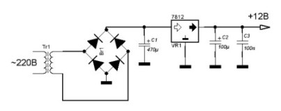
The power supply circuit is shown in Figure 3. The diode bridge is also made on diodes 1N4007, and the voltage regulator is + 12V on an integral stabilizer of type 7812. The power consumption is small, so you do not need to install the stabilizer on the radiator.
Figure 3. Thermostat power supply.
The design of the thermostat is arbitrary, most of the parts are mounted on a printed circuit board, it is better if the power supply is also mounted there. The transistor sensor is connected using a shielded two-wire cable, while the collector of the transistor is connected via a screen.
It is desirable that there is a three-pin connector at the end of the cable, and its counterpart on the board. You can also install a small-sized terminal block on the board, although this is less convenient than the connector. Such a connection will greatly facilitate the installation of the sensor and the entire device as a whole at the place of use.
The finished device should be placed in a plastic case, and install a temperature setting resistor R7 and LEDs HL1 and HL2 outside. It is better if these parts are also soldered on the board, and holes are made in the case for them.
The connection to the power network and the heater are connected through the terminal strip, which should be fixed inside the plastic case. To protect the entire device as a whole, the connection should be made according to the PUE, using protection equipment.
Several of these thermostats were made, and all of them showed acceptable accuracy of temperature control, as well as very high reliability, because with such simplicity of the circuit there is actually nothing to break.
Boris Aladyshkin
See also at bgv.electricianexp.com
:


