Categories: Featured Articles » Practical Electronics
Number of views: 170321
Comments on the article: 1
How to make a simple DIY welding machine
 To conduct water supply and sewerage, to make open-air cages for pets and birds, beautiful flower stands and many other things useful in the household, a welding machine made of available parts and materials will help you. With electrodes up to 4 mm in diameter, they can weld metal with a thickness of 1 - 20 mm. A home-made welding machine operates on AC 220 or 380 V.
Its basis is a three-phase step-down transformer 380/36 V, power 1 - 2 kW, designed to supply low voltage power tools. Even a copy with one burned-out winding is suitable.
Without disassembling the core, remove the secondary windings from all the coils by having a bite of the copper bus in several places. Do not touch the primary windings of the extreme coils, and rewind the middle one with the same wire, making bends every 30 turns. In total, they should be 8 - 10, so put on each tag with the number.
Then, on the two extreme coils, rewind the secondary winding until it is completely filled, using a three-phase multi-core power cable consisting of three wires with a diameter of 6-8 mm and one thinner. It withstands high currents, has reliable insulation, thanks to its flexibility it is possible to perform tight winding without first disassembling the unit. In total, about 25 m of such a cable will go. It can be replaced with a wire of a smaller cross section, folding the wires when winding in half.
The work is more convenient to carry out together: one puts the turns, and the other stretches the wire.
Make terminals for the leads of the secondary winding of the welding transformer from a copper tube with a diameter of 10 - 12 mm and a length of 30 - 40 mm. Rivet it on one side and drill a hole with a diameter of 10 mm in the turning plate, and on the other side insert carefully stripped wires, crimp them with light hammer blows, and then make core cuts on the surface of the tube to improve contact.
From the panel located on the top of the transformer, remove the standard screws with nuts and replace them with two new M10 threads (preferably copper) - the secondary winding terminals will be connected to them.
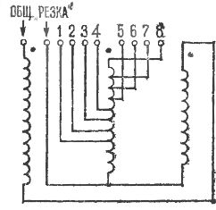
For the primary windings, make a separate additional PCB board of 3 mm thickness and attach to the transformer, as shown in the figure. Pre-drill 10-11 holes in it with a diameter of 6 mm and insert the MB screws with two nuts and washers into them. If the device will be powered by a 220 V network, connect the two extreme windings in parallel, and connect the middle one in series (see the electrical circuit of the transformer).
Even better, the installation works from a 380 V network. In this case, connect all the primary windings of the welding transformer in series - first two extreme ones, and then the middle one. Connect the terminals of the extreme windings to the common terminal, and the other two to the “Cutting” terminal. The taps of the middle winding will go respectively to the terminals "1", "2", "3", etc. The middle winding of the welding transformer serves as an additional inductive resistance in the extreme circuit, reducing the voltage and current in the secondary winding.

Wiring diagram for welding transformer windings

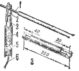
Electrode holder: 1 - electrode, 2 - spring, 3 - pipe, 4 - rubber hose, 5 - screw and nut M8, 6 - cable
The electrode holder (see fig.) Is made of a 3/4 "pipe with a length of 250 mm. On both sides of the pipe at a distance of 40 and 30 mm from its ends, cut a half-diameter hole with a hacksaw. And so that the electrode can be pressed to the holder, weld to pipe over a larger recess a piece of steel wire with a diameter of 6 mmOn the opposite side, drill a hole with a diameter of 8.2 mm and using a copper terminal and screw M8 with a nut, connect to the holder a piece of the same cable as the secondary winding. Put a rubber or nylon hose with a suitable inner diameter on top of the pipe.
The welding machine is connected to the network through a switch with wires with a cross section of at least 1.5 mm2 - one to the "General" terminal and the other to one of the terminals "1" - "8" (depending on the magnitude of the welding current). The highest current will be when connected to the "Cut" terminal.
The primary current of the welding transformer does not exceed 25 A, and the secondary current varies from 60 to 120 A.
Do not forget that the welding machine is designed to perform a relatively small amount of work. Therefore, after using 10 to 15 electrodes with a diameter of 3 mm, it must be allowed to cool. Accordingly, with electrodes with a diameter of 4 mm, the continuous operation of the installation is hidden to reduce even more. But with electrodes with a diameter of 2 mm, you can act without forced interruptions (the heating temperature of the transformer does not exceed 70 - 80 °).
In the "Cutting" mode, the welding machine heats up most quickly, therefore, in this case, it should also "rest" more often. You can cut metal of almost any thickness used in everyday life.
When switching from one welding mode to another, do not forget to turn off the power switch.
Read about how to make a spot welding machine yourselfhere.
See also at bgv.electricianexp.com
:

