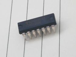
Chip 4046 (K564GG1) for devices with resonance retention - the principle of operation
 When creating a power electronic device with resonance retention in the LC circuit, a resonant controller circuit is designed to synchronize the received oscillations with control pulses coming from the driver. The task of this controller is to keep the resonant oscillations in the LC circuit by exciting it in time with its own oscillations.
The controller needs to receive a signal from the loop from the loop containing data on the current frequency and phase of free oscillations in it, after which, relying on these data, support the driver stage in synchronization with these frequencies and phases, then the resonance in the loop will automatically save. To build such a controller, the CD4046 chip or its domestic counterpart K564GG1 is suitable. Let's look at the device of this microcircuit, the purpose of its conclusions and the connection diagram of the mounted componentsto understand what you are dealing with if necessary ...
Simple RC circuit for rectangular pulse delay
 During the development of a pulse converter controller, for example, to construct a circuit with resonance retention, it may be necessary to delay the edges of the pulses and the decay of the pulse sequence when a rectangular signal is applied from one block of the circuit to another.
Sometimes a simple circuit consisting of two logical inverters and an RC circuit is suitable for solving this problem. For this purpose, it is convenient to use a microcircuit, which is a set of inverters with sufficiently defined thresholds. An example of such a microcircuit is 74N0404, there are 6 “NOT” logic elements in it, and it turns out that on one such microcircuit it is theoretically possible to construct 3 delay circuits according to the scheme below. In practice, when the decay of the rectangular pulse arrives at the input of the first inverter, the leading edge comes to the RC circuit from its output, and the capacitor starts charging ...
Bootstrap capacitor in a half-bridge control circuit
 Integrated circuits - half-bridge drivers, such as, for example, IR2153 or IR2110, involve the inclusion in the general circuit of a so-called bootstrap (detached) capacitor for independent power supply to the upper key control circuit. While the bottom key is open and conducting current, the bootstrap capacitor is connected through this open bottom key to the negative power bus, and at this time it can receive charge through the bootstrap diode directly from the driver's power source.
When the lower key is closed, the bootstrap diode stops supplying charge to the bootstrap capacitor, because the capacitor is disconnected from the negative bus at the same moment, and now can function as a floating power source for the gate control circuit of the upper half-bridge key. Such a solution is quite justified, because the power often required for key management is relatively small, and the energy spent can simply be periodically replenished ...
Schmitt trigger - general view
 During the design of the pulse circuit, the developer may need a threshold device that could form a pure rectangular signal with certain values of high and low voltage levels from the input signal of a non-rectangular shape (for example, sawtooth or sinusoidal). The Schmitt trigger, a circuit with a pair of stable output states, which under the action of the input signal, replace each other in a jump, fits well, that is, the output is a rectangular signal.
A characteristic feature of the Schmitt trigger is the presence of a certain range between the voltage levels for the input signal, when the output voltage of the input signal is switched over at the output of this trigger from a low level to a high one and vice versa. This property of a Schmitt trigger is called hysteresis, and the portion of the characteristic between the threshold input values ...
Discrete Component Field Effect Transistor Driver
 It’s one thing when there is a ready-made driver in the form of a specialized microcircuit like UCC37322 for high-speed control of a powerful field-effect transistor with a heavy gate, and it’s quite another when there is no such driver, and the power switch control scheme needs to be implemented here and now.
In such cases, it is often necessary to resort to the help of discrete electronic components that are available, and from them to assemble the shutter driver. The case, it would seem, is not tricky, however, in order to obtain adequate timing parameters for switching the field effect transistor, everything must be done efficiently and work correctly. A very worthwhile, concise and high-quality idea with the aim of solving a similar problem was proposed back in 2009 by Sergey BSVi in his blog. The circuit was successfully tested by the author in the half-bridge at frequencies up to 300 kHz. In particular, at a frequency of 200 kHz, with a load capacitanceat 10 nF ...
Choosing a driver for MOSFET (example calculation by parameters)
 FET gate control is an important aspect in the development of any modern electronic device. For example, when only the bottom is used in a pulse converter power key, and the decision was made in favor of using an individual driver in the form of a specialized chip, it is necessary to solve the problem of selecting a suitable driver so that it can satisfy the following conditions.
First, the driver will need to provide reliable opening and closing of the selected key. Secondly, it is necessary to comply with the requirements for an adequate duration of the leading and trailing edges during switching. Thirdly, the driver itself should not be overloaded while working in the circuit. At this stage, it is advisable to start by analyzing the data from the documentation for the field-effect transistor, and from them, determine what the characteristics of the driver should be ...
RCD snubber - principle of operation and calculation example
 During the development of a power pulse converter (especially for powerful push-pull and forward topology devices, where switching occurs in hard modes), care must be taken to protect the power switches from voltage breakdown.
Despite the fact that the fieldwork documentation indicates the maximum voltage between the drain and source at 450, 600 or even 1200 volts, one random high-voltage pulse on the drain may be enough to break the expensive (even high-voltage) key. Moreover, neighboring elements of the circuit, including a scarce driver, may come under attack. Such an event will immediately lead to a bunch of problems: where to get a similar transistor? Is it on sale now? If not, when will it appear? How good will the new fieldwork be? Who, when and for what money will undertake to solder all this? ...
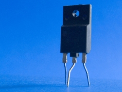
Inch * degree / watt - what is this radiator parameter?
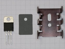 When approaching the question of choosing a radiator for a power transistor or a powerful diode, we, as a rule, already have the result of preliminary calculations regarding the power that the component will need to dissipate through the radiator against the surrounding air. In one case, it will be 5 watts, in the other 20, etc.
To dissipate more power, you need a radiator with a larger surface contact area with air, and if for the same transistor operating in the same mode, take a smaller radiator, then the radiator will be more heated.Thus, the statement is true for the same key: the larger the surface area of the radiator in contact with air, the more heat will be dissipated, and the less the radiator will heat up. That is, the longer the radiator and the more branched its profile is, the better it will dissipate heat and, accordingly ...
How to check the differential machine and RCD
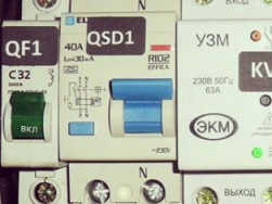 Residual current circuit breakers residual current circuit breakers are designed to disconnect power when a leakage current occurs. This is often called differential protection. However, any switching device must be checked, both for operation as such, and for compliance with the nominal parameters.
Does the residual current device as they are called "RCDs" operate when the current difference between the poles. In simple terms, the principle of operation of these devices is to compare the current through phase and zero. If the current through the phase is greater than zero, it means that part of it flowed in a different way, for example, insulation of the conductors was damaged or the heating element broke and a current of a certain magnitude "flows" to the ground. If the body of the appliance is grounded - this situation is not too terrible and even with good grounding is not even dangerous, but if you have a two-wire power supply network without grounding,then on hit potential ...
Export from Sprint-Layout - to Gerber format for ordering board production
 In recent years, many have ordered the manufacture of printed circuit boards in China. And this is not at all surprising, because on Aliexpress alone there are a huge number of enterprises offering for an affordable price to manufacture printed circuit boards in any quantity, and even with free international delivery.
But there is one feature in this process: all PCB manufacturers require sending project files exclusively in Gerber format to them. The reason for this provision is that Gerber is a file format that is very convenient for modern equipment, which is a way of textual description of all the smallest elements of a PCB design in the form of easily reproducible commands. However, not everyone who is interested in the manufacture of printed circuit boards and is engaged in the development of electronics only at an amateur level ...
 LEDs are the most efficient of all common light sources to date. Problems also lie behind efficiency, for example, the high requirement for the stability of the current that feeds them, and the poor tolerance of complex thermal operating conditions (at elevated temperatures). Hence the task of solving these problems. Let's see how the concepts of power supply and driver differ. To begin with, let's delve into the theory.
A power supply unit is a generic name for a part of an electronic device or other electrical equipment that supplies and regulates electricity to power this equipment. It can be located both inside the device and outside, in a separate case. A driver is a generic name for a specialized source, switch, or power regulator for specific electrical equipment. There are two main types of power sources ...
What is voltage, how to lower and increase voltage
 Voltage and amperage are the two main quantities in electricity. In addition to them, a number of other quantities are also distinguished: charge, magnetic field strength, electric field strength, magnetic induction and others. A practicing electrician or electronic engineer in everyday work most often has to operate with voltage and current - Volts and Amps. In this article, we will talk specifically about tension, about what it is and how to work with it.
Voltage is the potential difference between two points, characterizes the work performed by the electric field to transfer charge from the first point to the second. Measured voltage in Volts. This means that voltage can be present only between two points in space. Therefore, it is impossible to measure the voltage at one point. Voltage is measured with a voltmeter. The voltmeter probes connect voltage to two points or to the terminals of the part ...