Categories: Featured Articles » Sharing experience
Number of views: 34330
Comments on the article: 2
How to calculate and assemble a transformer using the Moment soldering iron as an example
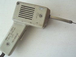 In the kit of the home master you must have soldering iron, sometimes even several different capacities and designs. The industry produces many different models, they are not difficult to purchase. The photo shows a working sample of the release of the 80s.
However, many craftsmen are interested in home-made designs. One of them at 80 watts is shown in the photos below.
This soldering iron was able to solder 2.5-square-square copper wires in the cold weather and to change transistors and other components of electronic circuits on printed circuit boards in the laboratory.
Principle of operation
The “Moment” soldering iron is powered by an ~ 220 volt electric network, representing an ordinary transformer, in which the secondary winding is shorted by a copper jumper. When turned on for a few seconds, a short circuit current flows through it, heating the copper tip of the soldering iron to temperatures that melt the solder.
The primary winding is connected by a cord with a plug to a socket, and a circuit breaker with mechanical spring self-resetting is used to supply voltage. When the button is pressed and held, a heating current flows through the tip of the soldering iron. As soon as you release the button, the heating stops immediately.
In some models, for the convenience of working in low light, from the primary winding by the principle of an autotransformer, a 4-volt tap is made that leads to a cartridge with a bulb from a flashlight. The directional light of the collected source illuminates the soldering spot.
Transformer design
Before starting the assembly of the soldering iron, you should determine its power. Typically, 60 watts is enough for simple electrical and radio amateur work. In order to constantly solder transistors and microcircuits, it is desirable to reduce power, and increase it for processing massive parts.
For manufacturing, you will need to use a power transformer of the appropriate capacity, preferably from old devices manufactured in the USSR, when all the electrical steel of the magnetic cores was produced according to the requirements of GOST. Unfortunately, in modern designs there are facts of manufacturing transformer iron from low-grade and even ordinary steel, especially in cheap Chinese devices.
Types of magnetic circuit
Iron must be selected according to the power of the transmitted energy. To do this, it is permissible to use not one, but several identical transformers. The shape of the magnetic circuit can be rectangular, round or W-shaped.
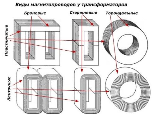
You can use iron of any shape, but it’s more convenient to choose armor plate because it has a higher power transfer efficiency and it allows you to make composite structures by simply adding plates.
When choosing iron, you should pay attention to the lack of air gap, which is used only in chokes to create magnetic resistance.
Simplified Methodology
How to choose iron for the required transformer power
We’ll make a reservation right away that the proposed methodology has been developed empirically and allows us to assemble a transformer from randomly selected parts at home, which works normally, but can, under certain circumstances, produce slightly different parameters from the calculated ones. This is not difficult to fix with a fine-tuning, which in most cases is not required.
The relationship between the volume of iron and the power of the primary winding of the transformer is expressed through the cross section of the magnetic circuit and is shown in the figure.
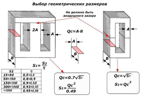
The power of the primary winding S1 is greater than the secondary S2 by the amount of efficiency ŋ.
The cross-sectional area of the rectangle Qc is calculated by the well-known formula through its sides, which are easy to measure with a simple ruler or vernier caliper. For an armored transformer, the amount of iron required is 30% less than for a rod transformer. This is clearly seen from the empirical formulas given, where Qc is expressed in square centimeters and S1 in watts.
For each type of transformer, according to its formula, the power of the primary winding is calculated through Qc, and then, through the efficiency, its value is estimated in the secondary circuit, which will heat up the soldering iron tip.
For example, if a W-shaped magnetic circuit is selected for 60 watts of power, then its cross section Qc = 0.7 ∙ √60 = 5.42 cm2.
How to choose the diameter of the wire for the transformer windings
As a material for the wire, copper should be used, which is coated with a layer of varnish for insulation. When winding coils on coils, varnish eliminates the appearance of inter-turn faults. The thickness of the wire is selected according to the maximum current.
For the primary winding, we know the voltage of 220 volts and decided on the primary power of the transformer, choosing a cross section for the magnetic circuit. Dividing the watts of this power into volts of the primary voltage, we obtain the winding current in amperes.
For example, for a 60-watt transformer, the current in the primary winding will turn out to be less than 300 milliamps: 60 [watts] / 220 [volts] = 0.272727 .. [amperes].
In the same way, the secondary current is calculated from its voltage and power values. In our case, this is not necessary: a winding of two turns, the voltage will be small, and the current will be large. Therefore, the cross section of the current lead is selected with a huge margin from the copper bus bar, which will minimize the loss from the electrical resistance of the secondary winding.
Having determined the current, for example, 300 mA, we can calculate the diameter of the wire according to the empirical formula: d wires [mm] = 0.8 ∙ √I [A]; or 0.8 ∙ √0.3 = 0.8 0.547722557505 = 0.4382 mm.
Such accuracy, of course, is not needed. The calculated diameter will allow the transformer to operate very long and reliably without overheating at maximum load. And we make a soldering iron, which periodically turns on for just a couple of seconds. Then it turns off and cools down.
Practice has shown that for these purposes, a diameter of 0.14 ÷ 0.16 mm is quite suitable.
How to determine the number of turns of the winding
The voltage at the terminals of the transformer depends on the number of turns and the characteristics of the magnetic circuit. Usually we do not know the brand of electrical steel and its properties. For our purposes, this parameter is simply averaged, and the entire calculation of the number of turns is simplified to the form: ώ = 45 / Qc, where ώ is the number of turns per 1 volt of voltage on any transformer winding.
For example, for the considered transformer of 60 watts: ώ = 45 / Qc = 45 / 5.42 = 8.3026 turns per volt.
Since we connect the primary winding to 220 volts, for it the number of turns will be ω1 = 220 ∙ 8.3026 = 1827 turns.
The secondary circuit uses 2 turns. They will give out a voltage of only about a quarter of a volt.
Making the frame for the coil
For a uniform distribution of turns of wire inside the magnetic circuit, it is necessary to make the frame of electrical cardboard, getinaksa or fiberglass. The technology of work is shown in the figure, and the sizes are chosen taking into account the design of the magnetic circuit. The windings insulated by the frame are arranged in a coil around which magnetic circuit plates are assembled.
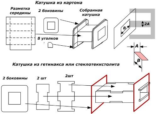
Often it is possible to use a factory frame, but if you need to add plates to increase power, you will have to increase the size. Cardboard parts can be sewn with ordinary threads or glued together. The body of fiberglass with accurate fitting of parts can be assembled even without glue.
In the manufacture of the coil, you must try to allocate as much space as possible to accommodate the windings, and when winding the coils, place them closely and evenly. When placing the wire, “lagged” may simply not have enough space and all the work will have to be redone.
Making a secondary soldering iron
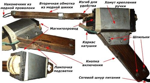
In the soldering iron shown in the photograph, the secondary winding is made of a copper bar with a rectangular cross section. Its dimensions are 8 by 2 mm. You can use other profiles. For example, it will be convenient to bend a round wire for placement inside the magnetic circuit. I had to work hard with a flat tire, use a vise, a hammer, templates and a file for uniform bending strictly according to the configuration of the coil frame.
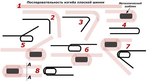
The figure in position 1 shows a flat tire. After making the frame, you need to determine its length, taking into account the distance that will go to the turns and the distance to the tip of a copper wire.
In position 2, it is approximately in the middle bending smoothly in a vise with small hammer blows in compliance with the orientation plane. When bending passes through a right angle, it is necessary to use a mild steel template with a shape that strictly matches the dimensions of the coil frame into which the winding will be placed.
The template greatly facilitates plumbing to give the winding the desired shape. Around it, at first one half of the splint is wrapped, which is shown at positions 4, 5 and 6, and then the other (see 7 and 8).
To facilitate understanding of the process, a sequence of bends is shown next to the images of the tire at positions with black lines with slight distortion.
At position 8, section AA is conventionally shown. Near it, it will be necessary to bend the tire 90 degrees for ease of operation, as shown in the photo.
If bends occur that prevent you from freely placing the power winding inside the coil frame, they can be cut off with a file. The turns of metal should not be in contact with each other and the body. To do this, they are separated by a layer of not thick insulation.
Holes are drilled at the ends of the secondary winding and a thread is cut to tighten the M4 screws. They serve to attach a copper tip made of 2.5 or 1.5 square wire. Since the voltage on the secondary winding is very small, the quality of the electrical contacts of the tip must be monitored, kept clean, clean of oxides and firmly squeezed with nuts and washers.
Making the primary winding of a soldering iron
After the power winding of the soldering iron is ready and insulated, it becomes clear how much free space is left in the coil for thin wire. With a deficit of space, the turns are tightly interconnected.
The winding wire consists of a copper core and one or several layers of varnish and is marked with PEV-1 (single-layer varnish), PEV-2 (two layers), PETV-2 (more heat-resistant than PEV-2), PEVTLK-2 (heat-resistant special).
By measuring the diameter of the wire with a micrometer, the result should be reduced by the thickness of the insulation. But this general recommendation is not critical for our soldering iron.
Considering the work in the conditions of heating, it is better to refuse from the PEV-1 brand, by the way, it is also not recommended to wind it up.
Usually the wire is wound on a reel on makeshift machines.
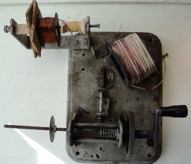
When a power winding is put on the frame, it will be necessary to do the turns manually and record their quantity on paper at a certain interval, for example, one hundred or two hundred.
Before starting work, it is necessary to solder to the beginning of the winding a stranded wire in strong insulation, preferably of the MGTF brand. It will withstand repeated bends, heat, mechanical stresses for a long time. The ends are connected by soldering, insulated. Flux is selected only rosin, acid is not allowed.
The flexible core is secured in the coil from being pulled out and brought out through an opening in the side wall. After winding, the second end of the winding is also soldered to the MGTF wire, which is brought out.
Since 220 volts will be supplied to the wire, it should be well insulated from the housing and the secondary winding.
Design refinement
After winding the coil, iron is tightly mounted on it, fixing it with wedges from falling out.Before the final assembly of the case, you can check the operation of the soldering iron by applying voltage to the primary winding to heat the tip and evaluate the current-voltage characteristic.
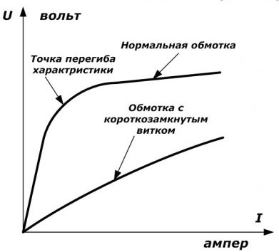
If the assembled structure solders well, then this can not be done. But, for information: it is advisable to guess the working point of the I – V characteristic at the point of inflection of the curve when the iron reaches its saturation. This is done by changing the number of turns.
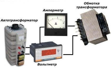
The determination method is based on the supply of an alternating voltage from an adjustable source to the transformer winding through an ammeter and a voltmeter. Several measurements are taken and a graph is plotted based on them, showing the fracture point (iron saturation). Then a decision is made to change the number of turns.
Handle, housing, switch
Any self-resetting button designed for currents up to 0.5 A is suitable as a switch. The photo shows a micro switch from an old tape recorder.
The handle of the soldering iron is made of two halves of solid wood, in which cavities are cut for placing wires, buttons and bulbs. In fact, backlighting is not necessary, for it you need to do a separate tap or resistive-capacitive divider.
The halves of the handles are tightened with studs and nuts. They also mounted a metal mounting clamp, which must be isolated from the iron of the magnetic circuit.
The self-made open housing design shown in the photo provides better cooling, but requires attention and safety rules from the employee.
Brave Alexei Semenovich
See also at bgv.electricianexp.com
:

