Categories: Featured Articles » Sharing experience
Number of views: 55739
Comments on the article: 1
How to connect a light bulb to a different voltage
 There are several ways to power a light bulb with a small voltage from an electric circuit with a high voltage. The article discusses the options for connecting the bulb to a different voltage by selecting additional resistance from a high-resistance wire and using diodes in series in the “forward direction”.
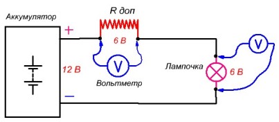
Suppose we need a light bulb rated for 6 volts and a current of 0.5 amperes turned on from a 12 volt battery. The simplest of the switching circuits consists of a light bulb connected in series, an additional resistance Rdop and a voltage source Ua, a battery.
It is necessary to select additional resistance in such a way that a voltage of 6 volts “drops” on a bulb with a current in the circuit I = 0.5 amperes. Resistance is performed from any high-resistance wire: nichrome, constantan, etc.
You can calculate the resistance value Rdop based on the resistivity of the high-resistance wire according to the formulas from Ohm's law. But there is one thing, BUT! To do this, you need to know that the wire is made of nichrome or other material and has the necessary parameters. You can’t determine this at a glance. And such a wire is usually "not at hand lying around." We will manufacture additional resistance "in a practical way."
It is necessary to use a high-resistance wire in isolation. But to get such a wire and for such a current is quite difficult. Therefore, we use what is at hand. Hardware stores sell coils for electric hobs or electric ovens. Such a high-resistance wire is quite suitable for our case. The wire is from 0.35 to 0.7 millimeters in diameter and can withstand our current I = 0.5 amperes.
Let's assemble a circuit for selecting the length of the wire.

To select the length of the wire and control the voltage in the circuit, we need a DC voltmeter for voltage up to 15 volts. The length of the spiral wire is chosen obviously longer than necessary. Starting from the longest end, the probe moves in a spiral.
Since the spiral is “bare”, without insulation, it needs to be slightly stretched so that the edges of the turns do not touch each other. Using a voltmeter, we control the voltage on the light bulb. When the voltage Ul on the bulb will be equal to 6 volts, this will correspond to the required length of the spiral wire and its resistance Rdop.
Since the wire is bare, it is wound on a frame of insulating material with a gap between the turns. If the wire on the frame does not fit in one layer, then lay the insulation, wind the second layer, etc.
The disadvantage of this method of reducing the voltage on the bulb (load) is that for a bulb with the same voltage but different power, you need additional resistance of a different magnitude, since the current in the electrical circuit will be different.
Or, if we connect another parallel to this bulb, their total resistance will be 6 Ohms, and the total resistance of the circuit will change. I will not give a calculation here by the formula of Ohm's law. I can only say that the current in the circuit will increase from 0.5 amperes to 0.67 amperes, the voltage on the resistor Rdop will increase to 8.0 volts, the voltage on two lamps in parallel will be equal to U = 4.0 volts, which is 2.0 volts less than necessary. The bulbs will burn in the light, which is not acceptable. This method of reducing the voltage across the load is suitable for both direct and alternating voltage.
There is another way to reduce the voltage at the load, but only for DC circuits.
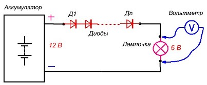
Instead of an additional resistor in the circuit, we include a chain of diodes connected in series in the “forward direction”.When the current flows through the diode, a "direct voltage" drops on it, equal, depending on the type of diode, its power and the current flowing through it, from 0.4 to 1.2 volts. On a germanium diode, it “drops” from 0.4 to 0.7 volts, on a silicon diode from 0.6 to 1.2 volts.
Based on how many volts you need to lower the voltage at the load, include the appropriate number of diodes. Compare two switching circuits: the previous one with an additional resistor and the new one with diodes.

In a circuit with a resistor in the circuit, the relationship between the current in the circuit and the voltage drop Udop is linear. How many times the current through the resistor will increase, the "voltage drop" Udop on it will increase by the same amount. On bulbs, however, the voltage drops from 6 volts to 4 volts.

A completely different picture will be if instead of a resistor we turn on a chain of diodes. The relationship between the current flowing through the diode and the voltage incident on it is nonlinear. The current can increase several times, the voltage drop across the diode will increase by only a few tenths of a volt.
Let's look at the volt - ampere characteristic of the diode. This is a curved line between the current and voltage on the diode. The line between points 0 - 4 is the output of the diode into rectification mode.
The line between points 4 - 7 onwards is an almost straight section. It can be seen that with a significant change in the current through the diode (several times), the voltage on the diode changes little (0.1 - 0.3 volts). This section is used to stabilize the voltage. Diodes must be selected according to the maximum current in the circuit.
The maximum allowable current of the diodes must be greater than the current in the calculated circuit. According to this scheme, I turned on a nine-volt portable radio from a 12-volt battery. Used a chain of 4 D226 diodes.
Victor Egel
See also at bgv.electricianexp.com
:


