Categories: Featured Articles » Sharing experience
Number of views: 116739
Comments on the article: 23

DIY computer power supply repair


General recommendations for the repair of computer power supplies for stationary computers.
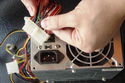
DIY computer power supply repairLow reliability RRussian electric networks is the cause of the failure of household equipment. In the system units of stationary computers, after the completion of the operating system, despite the apparent inaction, Power Supply remains permanently connected to the network. In this state, he is at risk of exposure to power surges.

The use of network filters is corrected only by the fact that they have a shutdown button, which is more effective protection than the specified protective and filtering functions.

Most system power supplies are assembled from ordinary, so-called non-name (no name) manufacturers. In this case, repairing the power supply does not justify the means.

But if you have installed a high-quality power supply of famous manufacturers and power exceeding 400 watts, then it is more reasonable to buy a new one may be an attempt to self-repair a failed power supply.

The first thing to remember is that life-threatening voltage of 220 volts is used in the power supply. The power supply circuit contains elements such as high-capacity capacitors that can store voltage for a long time. If you never held in your hands soldering iron, then it would be wiser for you to ask someone from your comrades, or think about buying a new one.

So, proceed to repair the computer power supply. You will hardly find such a concept on the Internet. There are several typical power supply circuits, so you have to navigate along the way.

Remove the cover of the power supply. Large radiators will be located on the board, necessary to remove heat from the power elements. Most of the malfunctions are the failure of these particular power elements located in the primary circuit.

For reliability, you should unsolder these elements (often you have to unsolder by braiding - take a braid, for example a shielding braid from a high-frequency cable, lean against a leg that needs to be soldered, a powerful soldering iron rests, dipped in rosin for a second. Solder from the board will tin off small braid hairs and gradually completely leave the board.

Attaching patience and accuracy, this method allows you to free a group of elements located, for example, on one radiator). Transistor test consists in dialing (checking for conductivity) transitions. Usually, not knowing the pinouts of the element, they begin to ring all the legs together. In a working transistor of a simple type, one leg should ring with the other two, while in the reverse polarity there should be no conductivity. It is the same between the other two - there should also not be calls. See more about this here: How to check the transistor.

To ensure the integrity of the elements, it is recommended to find their data (datasheet) on the Internet. To do this, in any search engine, type the word datasheet and the name of the transistor. The data will indicate the type of transistor, its composition (simple or composite) and the location of the "base", "collector" and "emitter".


We repeat that in the working transistor the base with the collector and the base with the emitter should ring in the same direction, and they should not ring in the opposite polarity (swap probes) and there should be no ringing between the collector and the emitter in both directions.

Suspected items are recommended to be replaced with new ones. Most items can be found in radio stores. If there are no such elements there, then the sellers will be able to find you analogues that are suitable for the characteristics.

Additionally, check nearby diodesmarked in the form of triangles with a transverse line at the top. They call in only one direction.

After replacing the defective elements, we carefully check the places of soldering for the presence of "nozzles" (jumpers with adjacent elements created during soldering). A test run of the power supply can be done by connecting a load of 12 volts (for example, a car bulb, or an old hard drive, etc.). Then we cross the "Power-on" terminal (usually green, the fourth from the edge of the largest connector) with the ground (next to it is the fifth black terminal).

If all defective elements are replaced, the power supply fan should start spinning. To be sure, it’s worth measure with a multimeter voltage on the main connectors. An integer value of the main voltages of 5 and 12 volts can say with confidence that the power supply is repaired.

In the event of an unsuccessful launch and a great desire to repair, you can try to ask a question at specialized radio technical forums. Usually regulars of such forums help with practical advice on what to pay attention to.

We wish you a stable voltage and long life to your power supply.

See also at bgv.electricianexp.com:

  • How to get twenty-four volts from a computer power supply
  • Universal power supply
  • LED strip power
  • The electrical circuit of the power supply for the garage
  • How to determine the compatibility of the power supply and the device

  •  
     
    Comments:

    # 1 wrote: Dred80 | [quote]


    From my experience repairing power supplies:
    1. Often electrolytic capacitors fail. Usually their malfunction can be determined by swollen appearance. To replace them, you need to find capacitors with the same parameters, you can replace them with capacitors of a slightly larger capacity. The main thing is that this voltage should be like that of replaceable capacitors.
    2. Due to the increase in voltage, transistors in the primary circuit burn out. In this case, the fuse insert usually burns out. Replace transistors with the same ones.
    3. The rectifier burns out. The input rectifier is usually changed to any other rectifier with the same parameters, you can use any diodes that are suitable for the parameters. If the rectifier burns out with an output, then ordinary diodes will not work here, you need to look for Schottky diodes.
    In most computer power supplies, a malfunction is detected by the appearance of the elements.
    When repairing for safety reasons, I always use an isolation transformer.

     
    Comments:

    # 2 wrote: | [quote]


    According to the experience of working as a radio mechanic (20 years of experience), most often there is a loss of the start pulse of the RF generator of the primary UPS circuits, the signal of formation of which is directly dependent on the processor and motherboard, as well as the correct operation of the operating system and BIOS. And without knowing the principle of work and the concept of the UPS DO NOT SHOULD HERE AND KOPS! I recommend not to skimp and buy a new one, otherwise after visiting your PSU with your hands there may be additional malfunctions and electric shock, in the best case additional expenses for electronic components are waiting for you.

     
    Comments:

    # 3 wrote: | [quote]


    A very valuable article!

    Only it should be called "Method of finding fault in the PSU PC."
    In general, complete nonsense! Nothing valuable and necessary.

     
    Comments:

    # 4 wrote: IgorAl | [quote]


    Old article. Who is now soldering the radio elements with a braid from the RF cable.
    And nobody needs you!

     
    Comments:

    # 5 wrote: andy78 | [quote]


    I do not quite understand what you all wanted? The complete practical guide "How to repair a computer power supply from A to Z"? So this book of pages can be written in three hundred and then all the nuances to the end can not be revealed. And here the author shared his personal experience in a short article on methods for determining faulty elements in the power supply and gave some tips for replacing them. Why is it nobody needs, pointless and out of date? In some simple cases, these tips may be helpful.And in complex ones, you have to have a power supply circuit and have a good understanding of modern electronics. But do not forget that this site is primarily for electricians, and not for electronic gurus, for whom some things seem commonplace.

    And as for the process of soldering radio elements with a braid from an RF cable, so if a person really uses this method and decided to share it, what's so bad? In addition, the author’s personal experience was very well supplemented with a comment on Dred80, for which many thanks to him. Here is a sample of a good comment! Guys, let's get more positive and do not hesitate to share your practical experience. And then everyone knows how to "snort". I don’t have to write my own article, where to sort things out and organize them on the shelves, and then get a bunch of grateful reviews for this article. Can anyone decide?

     
    Comments:

    # 6 wrote: Vladimir Khabarovsk | [quote]


    Brothers! Well, unless computer equipment can be repaired at the level of knowledge of radio engineering according to Borisov’s book “Young Radio Amateur”. This, as you might imagine, with the seeming simplicity, is the work of a professional, not a young technician. These are expensive experiments. Previously, it was special chic to tune the radio without any instruments! Try it now if you succeed. Greetings from the service center of Khabarovsk. Bring it. Help.s

     
    Comments:

    # 7 wrote: | [quote]


    So it means - immediately the first mistake in the description! - ".. We close the GREEN wire with the BLACK (ground) - ERROR. It must be so - close the 14th pin of the connector with the 15th (or 13th). I explain: Since the Chinese are very competent, sometimes they confuse GREEN (green ) with GRAY (gray), so sometimes where the green wire should be standard (14th pin), there is GRAY, and inexperienced masters make mistakes from this !!!

     
    Comments:

    # 8 wrote: IgorAl | [quote]


    The most important thing is that purple on black does not close when the power supply is plugged in!

     
    Comments:

    # 9 wrote: | [quote]


    Vladimir Khabarovsk Apparently, you are being discharged directly from the hospital with a soldering iron in Khabarovsk. Just professionals and grow out of young radio amateurs. And the money changers of burnt blocks come from the street. IMHO

     
    Comments:

    # 10 wrote: Nikola | [quote]


    "... marked in the form of triangles, with a transverse line at the top ..." People probably broke their heads - what is it?

     
    Comments:

    # 11 wrote: | [quote]


    BC does not respond to launch. Remove from the mother is fully working, power at all outputs is normal. Another unit on the mother is working. What to do? Tell me please.

     
    Comments:

    # 12 wrote: | [quote]


    Comments:

    # 13 wrote: | [quote]


    Scho could have come to grief, as if you were close to the world, you could have come to grips.

     
    Comments:

    # 14 wrote: | [quote]


    After komentov and I'm afraid to climb into the block. I have such a malfunction - the power supply does not turn off automatically, even when you press the button on the unit. It is necessary to disconnect the 220v supply manually on the outlet block. Can someone tell me what to do?

     
    Comments:

    # 15 wrote: | [quote]


    There is a question. The PSU broke one wire in front of the SATA connector. Will the PSU even work?

     
    Comments:

    # 16 wrote: andy78 | [quote]


    Infectedif repaired, it will work.

     
    Comments:

    # 17 wrote: | [quote]


    Tell me your thoughts. Burnt ups codegen. Changed power transistors and one diode from the bridge. I turned on 60vat through a light bulb. The light is on in the floor and there is a flickering 5sv, bp everything starts fine. But I can’t understand what burned out. The duty room seems to be working, all the diodes climbed and everything is in order on the high and after the trance. Without a bulb, a rectifying diode flies out.

     
    Comments:

    # 18 wrote: | [quote]


    I missed the "GREEN" and that "SIRIY." When tsomu wono pratsuvalo. Explain to whom?

     
    Comments:

    # 19 wrote: Alexei | [quote]


    Let me write! Gembird 400w broke. Repair is serious, interesting, I need experienced advice. As with all Gs, 1 power transistor 13009 even fired.it didn’t burn out, replaced both, rang the power and low harness, everything is in order, put the light bulb instead of the safety lock. I turn on it is silent, the 5.2V duty room keeps the load for a long time. When turned on, it goes out. m / sAT2005 9.10 leg pulses 0.5 s to 8 (generate) a good saw constantly. I connect another PSU in parallel, m / s wound up 9 (10) clear pulses reach the buildup transformer. On the high side of the impulse on one winding, short there is, on the other there is no (connection with the power cable) (where 13009 flew out) a large sine, changed the buildup trans without measurement. I hooked it to -300V. My suspicions: when the 2nd power supply is connected and the pulses are at the output. At m / with 12,13,14,16 legs 0v, but should 5v, 5v, 3,7v, 3,7v.13 PG 5v leg through 1k propped up, and there 0v. Yes, the requestor will be rewarded.

     
    Comments:

    # 20 wrote: Alexei | [quote]


    How much voltage should there be at the input of the buildup transformer at the midpoint to magnetize the TR (constant, if the duty officer gives only 5V and they go through the diode to the midpoint)? I have 0.7V if the power supply does not start. When connecting, add. bp all eg goes from 12v through the circuit and reaches the midpoint of 2.7v, it seems to me it will not be enough.

     
    Comments:

    # 21 wrote: | [quote]


    It is not always the replacement of old or failed elements that answers with the proper result - it is easier to buy a new unit - PRACTICE. And then, if in BP there are elements of a conditional period of which may be 5 years of service, then with frequent use of BP, the period is significantly reduced to the order of 2.5 ~ 3 years.

     
    Comments:

    # 22 wrote: vdb | [quote]


    Sergey wrote: According to the experience of working as a radio mechanic (20 years of experience), most often there is a loss of the start pulse of the RF generator of the primary UPS circuits, the signal of formation of which is directly dependent on the processor and motherboard, as well as the correct operation of the operating system and BIOS. Sergey, you would continue to work as a radio mechanic. Okay, I laughed and forgot, and someone inexperienced thread can believe in this nonsense.

     
    Comments:

    # 23 wrote: | [quote]


    With his own hands he killed the Linkworld LW2 350W (LPE). Incorrectly connected to the meterboard Albatron PX865PE Pro. Namely, the 4-pin connector that comes with the main 20-pin comb is connected as an add-on. Mom's nutrition. And for this, the PSU had a specially 4-pin connector. The motherboard remained intact. And BP - no. There is no way to start the fan by shorting a pair of contacts on a 20-pin comb. Tell me, is it possible to bring it back to life? Where to start the diagnosis. I'm weak in electrical engineering.