Categories: Featured Articles » Interesting Facts
Number of views: 43806
Comments on the article: 2
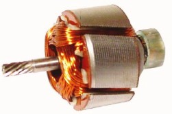
On the origin of the terms "anchor" and "rotor"
 Electrical term "anchor" much older than the word electrical engineering. In the era of great geographical discoveries and the development of navigation in the oceans, there was an acute need for magnetic compasses, the main part of which was the magnetic needle. These arrows were made of iron and magnetized by natural magnets. There were simply no others.
Good magnetization also required good magnets. To enhance the action of natural magnets, they were reinforced with iron, attaching it to the stone using non-magnetic frames made of copper, silver and even gold. All this was decorated with stylized figures, ornaments or inscriptions.
Magnets were expensive. The magnet set also included a removable iron block, which “stuck” to the poles of the magnet. This bar had on one side a ring, a hook or a decorative copy of the sea anchor for hanging a kettlebell. The holding power of this whetstone with a magnet could always be measured by the weight of the weights placed in the cup. The hook with the hook itself was called the “magnet anchor”.
With the invention of electromagnets in 1825, the method for measuring their strength has not changed. So, for example, in the preamble of his work, published in 1838 in St. Petersburg under the title "On the attraction of electromagnets," Russian academicians B.S. Jacobi and E.H. Lenz directly wrote down: "The force of attraction was determined by the weight of the weights, which were superimposed until the anchor broke off."
Electromagnets could already create powerful magnetic fields. The American scientist J. Henry created an electromagnet whose anchor was able to hold a tonne load. But this is not his main merit as an engineer. He anchored the electromagnet on the hinge and made it hit the bell with attraction. So the first electromagnetic bell appeared.
Having adapted the contacts to the movable armature, the American received a hitherto unknown device — a relay, a device for automatically switching electrical circuits by a signal from the outside, which allows transmitting telegraph signals at virtually any distance.
In modern electromagnetic relays, the moving part of the magnetic circuit is still called the anchor, although it does not have any external resemblance to the holding device of the ship on the roads.
The inventive thought of J. Henry did not stop there. He made a magnetic circuit with a coil and mounted it horizontally, like the beam of a laboratory analytical balance. When the device (armature) is swinging, the contacts fixed at the ends of the rocker arm periodically touched the terminals of two galvanic cells supplying the coil with currents of various directions. Accordingly, the rocker, swinging, was attracted to two permanent magnets included in the system.
The installation worked continuously, reporting an anchor of 75 swings per minute. So one of the first designs of a reciprocating electric motor appeared. However, to turn it into a rotational one for that time was not difficult.
Henry wrote: “I managed to set in motion a small machine by force, which until now has not been used in mechanics, I'm talking about magnetic attraction. I do not attach much importance to this invention, for in its present form it represents only a physical toy. However, it is possible that with the further development of the principle this can be used for practical purposes. ”
Machines with reciprocating motion did not receive distribution then, although quite functional designs were proposed by W. Clark, C. Page and others. An electric motor with a rotating armature turned out to be technologically more convenient in use.
Then came the era of three-phase alternating current. Nobody called the rotating components of AC motors an anchor, and this was true. How not to call a rotating magnetic field a vortex, but a rotating part rotor? But in DC machines (both in engines and generators), the terminology remains the same. The anchor rotates, and the pole tip is called a shoe, a word that can only be found in fairy tales of the 18th century.
Maybe it's worth changing the technology? Let's not rush. Now multiphase linear electric motors for monorail trains are gaining ground. Here, a tightly fortified monorail is used as a rotor, and windings mounted on a magnetic circuit of a rapidly racing electric locomotive are used as a stator (from the Latin one standing motionless). And is it necessary to change the established concepts, risking even more confusion?
See also at bgv.electricianexp.com
:
