Categories: Featured Articles » Interesting Facts
Number of views: 37323
Comments on the article: 4
Interesting facts about transformers
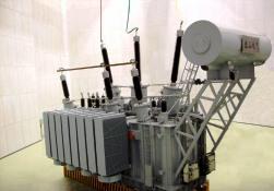 Each technical device has two birthdays: the discovery of the principle of operation and its implementation. The idea of a transformer after seven years of hard work on the “transformation of magnetism into electricity” was given by Michael Faraday.
On August 29, 1831, Faraday described in his diary an experiment that later went into all physics textbooks. On an iron ring with a diameter of 15 cm and a thickness of 2 cm, the experimenter wound separately two wires 15 and 18 m long. When a current flowed through one of the windings, the galvanometer arrows on the terminals of the other were deflected!
The scientist called a simple device "Induction coil". When the battery was turned on, the current (needless to say, constant) gradually increased in the primary winding. A magnetic flux was induced in the iron ring, the magnitude of which also varied. A voltage appeared in the secondary winding. As soon as the magnetic flux reached its limit value, the "secondary" current disappeared.
DIn order for the coil to work, the power source must be turned on and off all the time (manually - with a knife switch or mechanically - with a switch).
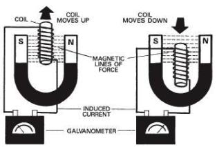
Faraday Experience Illustration
Faraday Induction Coil
Ppermanent or variable?
From the Faraday ring to the current transformer was far away, and science even then collected the necessary data on crumbs. The American Henry wrapped the wire with silk thread - insulation was born.
The Frenchman Foucault tried to rotate the iron bars in a magnetic field - and was surprised: they were heating up. The scientist understood the reason - the currents that were generated in an alternating magnetic field affected. To limit the path of the eddy currents of Foucault, Upton, an employee of Edison, suggested making the iron core prefabricated - from separate sheets.
In 1872, Professor Stoletov conducted a fundamental study on the magnetization of soft iron, and a little later, the Englishman Ewing presented to the Royal Society a report on energy losses during magnetization reversal of steel.
The magnitude of these losses, called “hysteresis” (from the Greek word “history”), really depended on the “past” sample. Grains of metal - domains, like sunflowers behind the sun, rotate after the magnetic field and are oriented along the lines of force. The work expended in this turns into heat. It depends on how - weakly or strongly - and in which direction the domains were directed.
Information on the magnetic and conductive properties accumulated gradually until the quantity turned into quality. From time to time, electrical engineers presented the world with surprises, but the main event in the history of transformers should be considered an event that made the world in 1876 turn in amazement towards Russia.
The reason was the candle Yablochkova. In the "lamps", an arc was burning between two parallel electrodes. At constant current, one electrode burned faster, and the scientist persistently sought a way out.
In the end, he decided, having tried many ways, to use alternating current, and lo and behold! - electrode wear has become uniform. Yablochkov’s act was truly heroic, because in those years there was a fierce struggle between electric lighting enthusiasts and the owners of gas companies. But not only that: the proponents of electricity themselves, in turn, unanimously opposed AC.
They received an alternating current, but few understood what it was. Long-term articles were published in newspapers and magazines that threatened the dangers of alternating current: "it is not the quantity that kills, but its change." The well-known electrical engineer Chikolev declared: “All machines with alternating current must be replaced with machines with direct current.”
No less prominent specialist Lachinov publicly blamed Yablochkova, because “direct current is good at all, and alternating current can only shine.”“Why should the gentlemen - adherents of candles (Yablochkov's arc candles) not try to seriously apply direct current to them; because with this and only this they could provide the future of candlelight, ”he wrote.
It is not surprising that under this pressure, Yablochkov finally threw his candles, but, in addition to partial “rehabilitation” of alternating current, he managed to open the true “face” of induction coils. His candles, connected in series, were extremely moody. As soon as one lamp-either the reason went out, everyone else instantly went out.
Yablochkov connected in series instead of “lamps” the primary windings of the coils. On the secondary, he "planted" candles. The behavior of each “lamp” did not at all affect the work of others.
True, the induction coils of the design of Yablochkov differed (and not for the better) from the Faraday ones - their cores did not close into a ring. But the fact that the alternating current coils worked continuously, and not periodically (when the circuit was turned on or off), brought the Russian inventor world fame.
Six years later, Usagin, a MSU medicine researcher, developed (or rather summarized) the idea of Yablochkov. Usagin connected different electrical devices (not just candles) to the output windings of the coils, which he called "secondary generators".
The coils of Yablochkov and Usagin were somewhat different from each other. Speaking in modern language, the Yablochkova transformer increased the voltage: in the secondary winding there were much more turns of thin wire than in the primary.
Usagin transformer is isolating: the number of turns in both windings was the same (3000), as well as the input and output voltages (500 V).
CALENDAR OF SIGNIFICANT DATES
Yablochkov’s induction coils and Usagin’s “secondary generators” began to acquire features that we know today with fabulous speed transformers.
1884 - the Hopkinson brothers closed the core.
Previously, magnetic flux went through a steel bar, and partially from the north pole to the south - through the air. Air resistance is 8 thousand times greater than that of iron. To obtain a noticeable voltage on the secondary winding was only possible for large currents passing through many turns. If the core is made into a ring or a frame, then the resistance is reduced to a minimum.
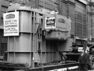
Transformer of the 1880s Brush electric light corporation
1885 - Hungarian Dery got the idea to turn on transformers in parallel. Prior to this, everyone used a serial connection.
1886 - the Hopkinsons again. They learned how to calculate magnetic circuits according to Ohm's law. At first, they had to prove that processes in electric and magnetic circuits can be described by similar formulas.
1889 - Swede Swinburne proposed cooling the core and transformer windings with mineral oil, which simultaneously plays the role of insulation. Today, Swinburne’s idea has been developed: a steel magnetic circuit with windings is lowered into a large tank, the tank is closed with a lid and after drying, heating, evacuation, filling with inert nitrogen and other operations, oil is poured into it.
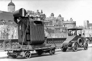
Transformer - late 19th - early 20th century (England)
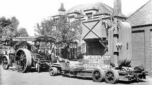
4000 kVA transformer (England) - beginning of 20th cent.
Toki. Up to 150 thousand a. These are the currents that feed furnaces for melting non-ferrous metals. In accidents, current surges reach 300-500 thousand a. (The transformer capacity on large furnaces reaches 180 MW, the primary voltage is 6-35 kV, on high-power furnaces up to 110 kV, secondary 50-300 V, and in modern furnaces up to 1200 V.)
Losses. Part of the energy is lost in the windings, part - for heating the core (eddy currents in the iron and hysteresis losses). Quick change of electrical and magnetic Pole in time (50 Hz - 50 times per second) forces molecules or charges in isolation to orient themselves differently: energy is absorbed by oil, bakelite cylinders, paper, cardboard, etc. d.
Pumps for pumping transformer hot oil through radiators take some power.
And yet, in general, the losses are negligible: in one of the largest transformer designs for 630 thousand kW, only 0.35% of the power gets stuck. Few devices can boast to. P. d. more than 99.65%.
Full power. The largest transformers are “attached” to the most powerful generators, so their powers coincide. Today there are 300, 500, 800 thousand kW power units, tomorrow these figures will increase to 1-1.5 million, or even more.
The most powerful transformer. The most powerful transformer manufactured by the Austrian company "Elin" and is designed for a thermal power plant in Ohio. Its power is 975 megavolt-amperes, it must increase the voltage generated by generators — 25 thousand volts to 345 thousand volts (Science and Life, 1989, No. 1, p. 5).
The eight largest single-phase transformers in the world have a capacity of 1.5 million kVA. Transformers are owned by the American company Power Power Service. 5 of them reduce voltage from 765 to 345 kV. ("Science and Technology")
In 2007, the Holding Company Elektrozavod (Moscow) manufactured the most powerful transformer previously produced in Russia - TC-630000/330 with a capacity of 630 MVA for a voltage of 330 kV, weighing about 400 tons. The new generation transformer was developed for the facilities of the Rosenergoatom Concern.
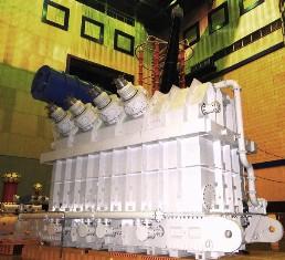
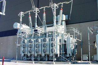
Domestic transformer ORTs-417000/750 with a capacity of 417 MVA for a voltage of 750 kV
Design. Any transformer for any purpose consists of five components: magnetic circuit, windings, tank, cover and bushings.
The most important detail - the magnetic circuit - is made up of steel sheets, each of which is coated on both sides with insulation - a varnish layer with a thickness of 0.005 mm.
The dimensions, for example, of the transformers of the Canadian power station Busheville (manufactured by the West German company Siemens) are as follows: height 10.5 m, cross-sectional diameter 30 - 40 m.
The weight of these transformers is 188 tons. Radiators, expanders and oil are poured from them when transported, and still the railway workers have to solve a difficult problem: 135 tons is no joke! But such a load does not surprise anyone: at the Obrichheim nuclear power plant there is a transformer group with a capacity of 300 thousand kW. The main “converter” weighs 208 tons, the adjustment one - 101 tons.
To deliver this group to the place, a 40-meter railway platform was required! It’s not easier for our power engineers: after all, the designs they create are among the largest in the world.
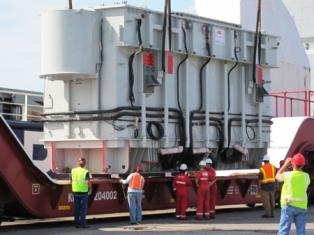
388 tons transformer! (USA)
Work. A large transformer lasts 94 days out of 100. The average load is about 55-65% of the calculated. This is very wasteful, but nothing can be done: one device will fail, its understudy quite quickly literally “burns out at work”. If, for example, the structure is overloaded by 40%, then in two weeks its insulation will wear out, as in a year of normal service.
Among students, there has long been a legend about an eccentric who answers the question “How does a transformer work?” "" Resourcefully "replied:" Oooo ... "But only today the reason for this noise becomes clear.
It turns out that it is not the vibration of steel plates that are poorly bonded to each other, the boiling of oil and the elastic deformation of the windings that are to blame. The cause can be considered magnetostriction, that is, a change in the size of the material during magnetization. How to deal with this physical phenomenon is still unknown, so the transformer tank is lined with soundproof shields.
The norms for the “voices” of transformers are quite strict: at a distance of 5 m - no more than 70 decibels (level of loud speech, car noise), and at a distance of 500 m, where residential buildings are usually located, about 35 decibels (steps, quiet music).
Even such a brief review allows us to draw two important conclusions. The main advantage of the transformer is the absence of moving parts. Due to this, a high k is achieved. P. d., excellent reliability, easy maintenance. The biggest drawback is the huge weight and dimensions.
And you still have to increase the size: after all, the power of transformers should grow several times in the coming decades.
Transformer Mitsubishi Electric - 760 MVA - 345 kV
HYMN
Transformers are the most motionless machines of technology. “THESE RELIABLE IRON DECK. .. ”So, emphasizing the simplicity of the design and the great weight, the Frenchman called Janvier called transformers.
But this immobility is apparent: the windings are surrounded by currents, and magnetic fluxes move along the steel core. However, seriously talking about the motion of electrons is somehow awkward. Charged particles barely creep along the conductors, moving in an hour just a half a meter. Between the moments of entry and exit of the “labeled” group of electrons, about a year passes.
Why, then, the voltage in the secondary winding occurs almost simultaneously with the inclusion? It is not difficult to answer: the speed of propagation of electricity is determined not by the speed of movement of electrons, but by the associated electromagnetic waves. Pulses of energy develop 100-200 thousand km per second.
The transformer "does not fuss", but this in no way speaks of its "internal" tendency to rest. The interaction of currents in the conductors leads to the appearance of forces tending to compress the windings in height, to shift them relative to each other, to increase the diameter of the turns. It is necessary to fetter the windings with bandages, struts, wedges.
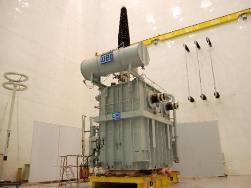 Bursting with internal forces, the transformer resembles a shackled giant striving to break chains. In this struggle a person always wins. But behind tamed cars you need an eye and an eye. About ten electronic, relay and gas shields are installed on each structure, which monitor the temperatures, currents, voltages, gas pressure and, at the slightest malfunction, turn off the power, preventing an accident.
We already know: the main drawback of today's transformers is their gigantism. The reason for this is also clear: it all depends on the properties of the materials used. So, maybe, if you search well, there will be other ideas for converting electricity, besides the one that Faraday once proposed?
Unfortunately (and maybe, fortunately - who knows), there are no such ideas yet, and their appearance is unlikely. As long as alternating current reigns in the energy sector and there remains a need to change its voltage, the idea of Faraday is beyond competition.
Since transformers cannot be abandoned, perhaps it will be possible to reduce their number?
You can "save" on transformers, if you improve the current supply system. The modern urban electricity network resembles the human circulatory system. From the main cable, branches “through a chain reaction” branch to local consumers. The voltage is gradually reduced by steps to 380 V, and at all levels it is necessary to install transformers.
English experts have developed in detail another, more profitable option. They offer to power London according to this scheme: a cable of 275 thousand, enters the city center. Here, the current is rectified, and the voltage "automatically" drops to 11 thousand volts, direct current is supplied to factories and residential areas, is again converted into alternating voltage and decreases in voltage. Several voltage levels disappear, fewer transformers, cables and related devices.
The frequency of current fluctuations in our country is 50 Hz. It turns out that if you go to 200 Hz, the weight of the transformer will be reduced by half! Here, it would seem, a real way to improve the design. However, with an increase in the frequency of the current by a factor of 4, the resistances of all elements of the power system and the total loss of power and voltage will increase at the same time. The mode of operation of the line will change, and its restructuring will not pay off with savings.
In Japan, for example, part of the power system operates at 50 Hz, and some at 60 Hz. What is easier to bring the system to one “denominator”? But no: this is not only hindered by private ownership of power plants and high-voltage lines, but also by the high cost of upcoming alterations.
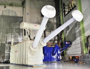
ABB Transformer
The size of transformers can be reduced by replacing today's magnetic and conductive materials with new, much better properties. Something has already been done: for example, built and tested superconducting transformers.
Of course, cooling complicates the design, but the gain is obvious: current densities increase to 10 thousand, and against the previous one (1 a) for each square millimeter of the wire cross section. However, only a very few enthusiasts risk betting on low-temperature transformers, because the benefit on the winding is completely neutralized by the limited capabilities of the steel magnetic circuit.
But here in recent years there has been a way out: either to bind the primary and secondary windings without an intermediary - steel, or to find materials that are better than iron in magnetic properties. The first way is very promising, and such "air" transformers have already been tested. The windings are enclosed in a box made of a superconductor - an ideal “mirror” for a magnetic field.
The box does not let the field out and does not allow it to disperse in space. But we have already said: the magnetoresistance of air is very large. You will have to wind too many "primary" turns and apply too high currents to them to get a noticeable "secondary".
Another way - new magnets - also promises a lot. It turned out that at very low temperatures holmium, erbium, dysprosium become magnetic, and their saturation fields are several times greater than that of iron (!). But, firstly, these metals belong to the rare-earth group, and therefore are rare and expensive, and, secondly, the hysteresis losses in them will, in all likelihood, be much higher than in steel.
V. Stepanov
According to the materials of the journal "Youth Technology"
See also at bgv.electricianexp.com
:


