Categories: Featured Articles » Interesting Facts
Number of views: 41767
Comments on the article: 4
What is Tesla Transformer
Today, the Tesla transformer is called a high-frequency high-voltage resonant transformer, and in the network you can find many examples of vivid implementations of this unusual device. A coil without a ferromagnetic core, consisting of many turns of a thin wire, crowned with a torus, emits real lightning, impressing amazed spectators. But do everyone remember how and why this amazing device was originally created?
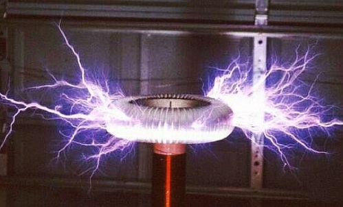
The history of this invention begins in the late 19th century, when a brilliant experimental scientist Nikola Teslawhile working in the USA, he only set himself the task of learning how to transmit electrical energy over long distances without wires.
It is hardly possible to pinpoint the specific year when this idea came to the scientist for sure, but it is known that on May 20, 1891, Nikola Tesla gave a detailed lecture at Columbia University, where he presented his ideas to the staff of the American Institute of Electrical Engineers and illustrated showing visual experiments.
The purpose of the first demonstrations was to show a new way of obtaining light by using high frequency and high voltage currents for this, as well as to reveal the features of these currents. In fairness, we note that modern energy-saving fluorescent lamps work on the principle that was just proposed for Tesla's light.
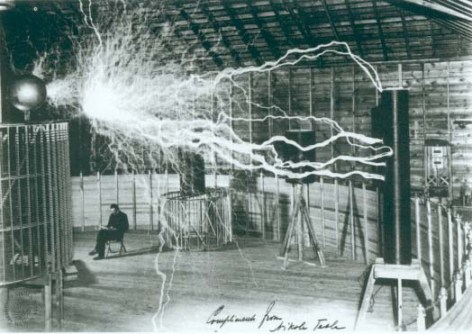
Final theory regarding exactly wireless electric power transmission it loomed gradually, the scientist spent several years living up to mind his technology, experimenting a lot and painstakingly improving each element of the circuit, he developed breakers, invented resistant high-voltage capacitors, invented and modified circuit controllers, but he could not bring his plan to life on the scale in which he wanted.
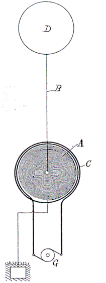
However, the theory has reached us. Diaries, articles, patents and lectures by Nikola Tesla are available, in which you can find the initial details regarding this technology. The principle of operation of a resonant transformer can be found by reading, for example, Nikola Tesla's patents No. 787412 or No. 649621, already available today on the network.
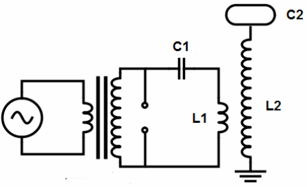
If you try to briefly understand how the Tesla transformer works, consider its structure and principle of operation, then there is nothing complicated.
The secondary winding of the transformer is made of insulated wire (for example, from an enamel wire), which is laid round to round in a single layer on a hollow cylindrical frame, the ratio of the height of the frame to its diameter is usually taken from 6 to 1 to 4 to 1.
After winding, the secondary winding is coated with epoxy resin or varnish. The primary winding is made of a relatively large cross-section wire, it usually contains from 2 to 10 turns, and fits into the shape of a flat spiral, or is wound like a secondary one - on a cylindrical frame with a diameter slightly larger than that of the secondary one.
The height of the primary winding, as a rule, does not exceed 1/5 of the height of the secondary. A toroid is connected to the upper terminal of the secondary winding, and its lower terminal is grounded. Next, consider all in more detail.
For example: the secondary winding is wound on a frame with a diameter of 110 mm, PETV-2 enamel wire with a diameter of 0.5 mm, and contains 1200 turns, so its height is about 62 cm, and the length of the wire is about 417 meters. Let the primary winding contain 5 turns of a thick copper tube, wound around a diameter of 23 cm, and has a height of 12 cm.
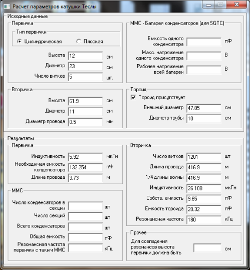
Next, make a toroid. Its capacitance should ideally be such that the resonant frequency of the secondary circuit (grounded secondary coil together with the toroid and the environment) corresponds to the length of the secondary winding wire so that this length equals a quarter of the wavelength (for our example, the frequency is equal to 180 kHz) .
For accurate calculation, a special program for calculating Tesla coils, for example VcTesla or inca, can be useful.A high-voltage capacitor is selected for the primary winding, the capacitance of which, together with the inductance of the primary winding, would form an oscillatory circuit, whose natural frequency would be equal to the resonant frequency of the secondary circuit. Typically, a capacitor close in capacity is taken, and tuning is carried out by selection of turns of the primary winding.
The essence of the Tesla transformer in canonical form is as follows: the primary circuit capacitor is charged from a suitable high voltage source, then it is connected by the switch to the primary winding, and so it is repeated many times per second.
As a result of each switching cycle, damped oscillations occur in the primary circuit. But the primary coil is an inductor for the secondary circuit; therefore, electromagnetic waves are excited in the secondary circuit, respectively.
Since the secondary circuit is tuned to resonance with the primary oscillations, a voltage resonance arises on the secondary winding, and so the transformation coefficient (the ratio of the primary winding turns and the secondary windings covered by it) must also be multiplied by Q - the quality factor of the secondary circuit, then the real ratio voltage on the secondary winding to voltage on the primary.
And since the length of the wire of the secondary winding is equal to a quarter of the wavelength of the oscillations induced in it, it is on the toroid that there will be a voltage antinode (and at the ground point - the current antinode), and this is where the most effective breakdown can take place.
Different circuits are used to power the primary circuit, from a static spark gap (spark gap) powered by MOTs (ILO - a high-voltage transformer from a microwave oven) to resonant transistor circuits on programmable controllers powered by a rectified mains voltage, however, the essence of this does not change.
Here are the most common types of Tesla coils, depending on how you control them:
SGTC (SSTC, Spark Gap Tesla Coil) - Tesla transformer in the spark gap. This is a classic design, a similar scheme was originally used by Tesla himself. As a switching element, a spark gap is used here. In low-power structures, the arrester is two pieces of thick wire located at some distance, while in more powerful ones, complex rotating dischargers using motors are used. Transformers of this type are made if only a large length of the tape drive is required, and efficiency is not important.
VTTC (WTC, Vacuum Tube Tesla Coil) - Tesla transformer on an electronic lamp. As a switching element, a powerful radio tube, for example GU-81, is used here. Such transformers can operate continuously and produce fairly thick discharges. This type of power is most often used to build high-frequency coils, which, due to the typical appearance of their streamers, are called “torches”.
SSTC (SSTC, Solid State Tesla Coil) - Tesla transformer, in which semiconductors are used as a key element. Usually this IGBT or MOSFET Transistors. This type of transformer can operate continuously. The appearance of streamers created by such a coil can be very different. This type of Tesla transformer is easier to control, for example, you can play music on them.
DRSSTC (DRSTC, Dual Resonant Solid State Tesla Coil) - Tesla transformer with two resonant circuits, here, as keys in SSTC, semiconductors are used. ДРССТЦ - the most difficult type of Tesla transformers in control and tuning.
To obtain more efficient and effective operation of the Tesla transformer, it is DRSSTC topology schemes that are used, when powerful resonance is achieved in the primary circuit itself, and in the secondary, respectively, a brighter picture, longer and thicker lightnings (streamers).
Tesla himself tried as best he could to achieve just such a mode of operation of his transformer, and the beginnings of this idea can be seen in patent No. 568176, where charge reactors are used, then Tesla developed the circuit along this path, that is, he sought to use the primary circuit as efficiently as possible, creating resonance. You can read about the scientist’s experiments in his diary (the scientist’s notes on experiments in Colorado Springs, which he conducted from 1899 to 1900, have already been published in printed form).
Speaking about the practical application of the Tesla transformer, one should not confine oneself to admiration for the aesthetic nature of the discharges received, and treat the device as a decorative one. The voltage on the secondary winding of the transformer can reach millions of volts, which in the end is an effective source of ultra-high voltage.
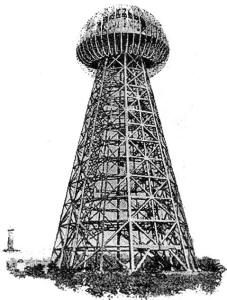
Tesla himself developed his system for transmitting electricity over long distances without wires, using the conductivity of the upper air layers of the atmosphere. It was assumed that there was a receiving transformer of a similar design, which would lower the accepted high voltage to a value acceptable to the consumer, you can find out about this by reading Tesla's patent No. 649621.
Of particular note is the nature of the Tesla transformer's interaction with the environment. The secondary circuit is an open circuit, and the system is not thermodynamically isolated, it is not even closed, it is an open system. Modern research in this direction is conducted by many researchers, and a point on this path has not yet been set.
See also at bgv.electricianexp.com
:
