Categories: Electrician at home, Electrical Reviews
Number of views: 54582
Comments on the article: 4
ABP for single-phase network and phase switch PF-451
 In industrial power supply, the term is used in the form of a simple abbreviation: ABP. Automatic input of power reserve is possible if there is an additional, backup source of power supply. In fact, such a backup source most often becomes an additional backup line, generator or battery installation. Automatic transition to backup power is carried out using relays or special electronic units.
But for a household network, such things seem superfluous: relays, electronic components, a backup line, a generator set ... It's cheaper and easier to sit without electricity, or in the light of a flickering lamp that suffers from unstable or undervoltage.
However, it should be remembered that the household network of an apartment or private house in the vast majority of cases is single-phase. And the power line is almost always three-phase. One of the phases feeds our apartment, and the other two? Why aren't these backup lines?
Indeed, it is not so rare that malfunctions occur in only one phase of the network: a burned-in insert in the switchgear, voltage sagging due to phase imbalance, an elementary break - it is very unpleasant when all this happens in the phase from which you powered up. Therefore, it is quite understandable that the intention is to bring all three phases into the input shield, and here, in place, to organize between these three phases mutual automatic switching in case of a malfunction. It is only necessary to take measures that exclude interphase short circuit.
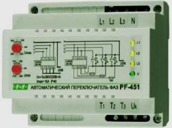
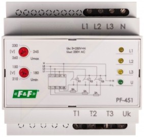
Technically, all this can be implemented on relay blocks, but it is easier to use off-the-shelf technical solutions based on special electronic devices, such as an automatic phase switch PF-451 manufactured by Euroavtomatika LLC.

This device has four input and four output terminals: three phases and a working neutral. The input terminals are labeled L1, L2, L3 and N. Terminal N is required to connect the working neutral and measure the voltage. Output terminals - T1, T2, T3 and UK. The terminal UK is intended for connection of a phase wire of a network.
The device is simple - three built-in relays, of which only one can keep its contacts closed at some arbitrary point in time. The selection of this “happy relay” is carried out automatically when determining the phase with a voltage closest to 220 volts.
While the voltage in the phase is stable and normal, the device keeps the contacts of the corresponding relay closed, and the single-phase network is powered from this phase. But if the voltage of the phase “subsided” or disappeared altogether, then within a split second the device will turn off this built-in relay and close the contacts in another phase: in the one that has not been affected by the problem.
The consumer may not even notice that his network has switched to another phase. At the same time, the PF-451 does not have “priority” phases; it simply works with the current phase until any problems occur in it.
The simplest connection diagram for the PF-451 phase switch is a direct circuit: three phases and zero are connected to the input terminals, and all four output phases are connected by jumpers and connected to the phase conductor of the network. The zero conductor goes to the network in addition to the device.
Such a scheme is extremely simple to assemble, but it has one obvious drawback. When it is implemented, the entire load current of the network will flow through the device. The contacts of the built-in relays are designed for a maximum of 16 amperes, and this is a very small load. 16 amperes can be consumed by one line of sockets, and a house or apartment electrical input is designed for at least 25 amperes, but more often - for 40-50 amperes.
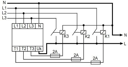
Wiring diagramphase switch PF-451
In addition to the PF-451 phase selector, three contactors (starters) with 220 volt control coils will have to be used to create an automatic transfer switch for input with a load of more than 16 amperes. And then the terminals T1, T2 and T3 will no longer be combined: each of them will be connected to one of the terminals of the coil of its contactor.
The second output of the coil is connected to the working neutral. The phase wire of the network in the circuit with contactors is also connected to the terminal Uk to control the output voltage, but in addition this wire is connected to the output power terminals of all three contactors.
The same three phases are connected to the input terminals of the contactors as to the input terminals of the device L1, L2 and L3. Thus, the device no longer supplies electricity to the network on its own, but simply controls the contactors, the power contacts of which can hold the required current, provided that the contactors are selected correctly.
Thus, in the presence of a single-phase 220 volt network and a three-phase 380 volt line, the PF-451 phase switch allows without any difficulties to realize a full-fledged ABP circuit even for a novice electrician.
Alexander Molokov
See also at bgv.electricianexp.com
:

