Categories: Featured Articles » Home automation
Number of views: 64538
Comments on the article: 2
How to mount and connect a streetlight with motion and light sensors
The term "spotlight" explains the explanatory dictionary of the Russian language as a lighting device, consisting of a system of mirrors or optical lenses, designed to create a strong stream of directional light focused in a limited angle.
It has a large blinding effect and, when installed on vehicles, it must be switched off when the oncoming stream is much earlier than the main beam headlights. Such structures are practically not used to illuminate the entrance to buildings.
Over the past two decades, streetlights have come to be called ordinary street lights, illuminating the territory at a wide angle and having a power of 50, 20 and even 10 watts. They are equipped with economical LED sources, motion and light sensors.
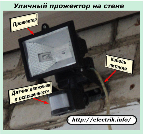
In most cases, they are already factory-installed and prepared for joint work. It is enough for the end user to connect power wires to them and adjust the regulators to their conditions so that the lamp starts to work in automatic mode.
How to connect a standard streetlight with a motion sensor
Inside the body of the kit of a similar lamp is terminal blockconnected to a mounted internal electrical circuit. She has collected 4 chains:
1. The brown wire of phase “L” is connected to the sensor;
2. the working zero "N" from the block diverges with two lines to the lamp and the sensor;
3. protective conductor "RE" from the terminal is wired to the housing;
4. the phase wire from the sensor switch "A" through the terminal block is connected to the lamp.
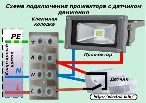
To connect the spotlight to the work, it is necessary to apply the phase, working and protective zeros with the power cable from the apartment shield, as shown in the figure with brown, blue and yellow-green wires.
After that, on the internal circuit, the phase and zero from the block will go to the motion and light sensors, preparing their power supplies, logic and executive parts for work. When conditions arise for the sensor to operate, the internal contact will close, which will apply the potential of phase "A" to the spotlight to turn it on.
The opening of this contact occurs after the cessation of movement within the observed space or the onset of normal illumination, which leads to the blackout of the light by a searchlight in automatic mode.
PE protective zero is designed to control and disable possible leakage currents in case of accidental violations of the wiring insulation inside the lamp. In buildings operated by TN-C systemIt is not used.
Thus, to connect a ready-made streetlight with a motion sensor, it is enough to connect the power wires L, N, PE to its block.
Features of installing a spotlight in place of old fixtures
Quite often, building owners simply change the old lights, controlled by a wall switch with new ones that work in automatic mode. In this case, you can use the already laid wiring without changing the circuit.
The searchlight will be controlled automatically after the switch is turned on and supplies the phase. If it is turned off, then there will be no light.
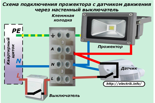
Since the owners of the building have different addictions, some of them bypass the contacts of the circuit breaker and fully trust the work of automation, while others prefer to combine both functions.
Some owners prefer the parallel connection of a motion sensor and a switch.
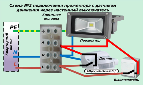
With this method, you can always turn on the lighting manually and block the automatic control function.For it to work, you will need to disconnect the parallel voltage supply circuit breaker.
From the point of view of automation, this scheme is not the most successful, but some people use it. True, the switch in most cases is simply turned off.
Features of the installation of motion and light sensors
Methods of mechanically securing a street spotlight must be performed so that the sensitive elements of the sensors are strictly directed into a controlled space.
How to adjust the position of the sensor
To explain, consider the radiation of infrared rays coming from the human body under normal conditions.
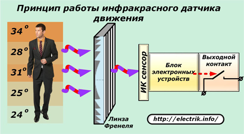
On the external plane of the sensor, heat fluxes are collected by the Fresnel lens, and after it are focused and directed to the infrared sensor of the pyrodetector. Then they are processed by the logic of the blocks of electronic devices, which include:
-
signal amplifier;
-
twilight switch;
-
time relay;
-
mode switch.
The result of the sensor is the closure or disconnection of its output contact, which is used to turn on or off the searchlight.
Based on this principle of operation, the motion sensor must be oriented so that the Fresnel lens is directed strictly at the controlled object, and not in the other direction.
How to position a spotlight in space for optimal performance
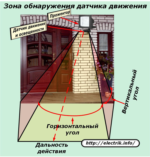
A lighting device propagates light at an angle from the optical system and is clearly visible. Therefore, adjusting the direction of the lamp is not difficult.
The touch dimmer controls a certain part of the space and perceives infrared rays from the sides where it was sent, taking into account its own technical capabilities.
When orienting the sensor, it must be taken into account that it has certain values:
1. range of action;
2. deviation angles in the vertical and horizontal planes.
The first characteristic estimates the distance to an object approaching the sensor at which it will start to work. If people do not reach the control zone, then the spotlight should not turn on. He is obliged to shine only when a person enters a space covered by vertical and horizontal angles, the values of which are given by technical characteristics and are indicated in the passport data.
To adjust the mechanical position of the sensor in space, there are usually rotary bodies with screw locks. For simple models, certain functions may be limited. In this case, you have to create additional structural elements yourself.
Features of setting motion and light sensors
After the spotlight and dimmer are oriented in space for normal operation of the entire structure, it is necessary to set the potentiometers of settings located on the housing, the values of the working settings for a clear operation of the illuminator.
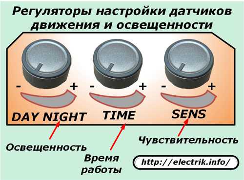
Usually there are three knobs for installation:
1. illumination - Day - Night;
2. time - Time;
3. Sensitivity - Sens.
Each potentiometer has a position indicator for the movable element of the regulator, and a scale on the stationary part of the housing, marked with the signs “-” and “+”. When turning any knob in the “+” direction, the potentiometer setting increases.
The light regulator empirically selects the degree of light that allows a person to be comfortably in the controlled area.
The potentiometer of time sets the pause of work, which determines the duration of the searchlight after people have stopped activities inside the illuminated space.
On budget models, the sensitivity control may not be available. It is used to roughen the range of action, when excessive triggering often occurs due to the appearance of various interference or the technical need to reduce the distance from the sensor to appearing objects.
Technology of installation of mechanical parts of the lamp
To mount the spotlight on the wall, a special bracket and ordinary self-tapping screws with dowels are used.
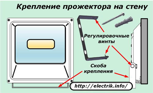
After determining the installation height of the illuminator through the marks in the bracket, holes are planned in the wall and drilled. Then, there they fasten the fastening bracket with screws and dowels and hang the case, orienting it in the corners of the vertical and horizontal plane.
On standard spotlights, motion sensors are already mounted on a common housing. They just need to be set and fixed with mechanical regulators.
How to connect a powerful streetlight to a motion sensor
Typical designs of luminaires with motion sensors may not always satisfy the specific needs of individual users. In illuminating large architectural objects or in critical protected areas, floodlights of increased power and extended range can be used, consuming a significant amount of energy. They are supplied separately, without picking up sensors for them.
If they are connected directly from the contact of a low-power sensor, the latter will not withstand the temperature load and burn. Therefore, in such cases, starters or contactors are used - devices that repeat the position of the output contact of the sensor, but do not create increased loads for it.
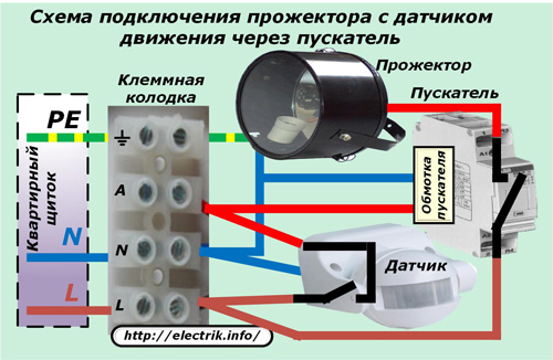
In the above scheme, the contact of a low-power sensor supplies voltage to the starter winding, the electrical resistance of which is large and does not create temperature overheating of the dimmer. At the same time, the power contact of this device reliably commutes the increased currents of a powerful searchlight.
Thus, the inclusion in the scheme of only one additional element - starter, repeating the work of the output contact of the motion sensor, allows you to control the work of very strong lamps.
When using this circuit, it is necessary to take into account the power of the output contact of the sensor and compare it with the load created by the starter winding in the same way as the ability of the power contact of the starter to withstand the currents generated by the searchlight.
The same scheme is suitable for the case when it is necessary to simultaneously control the operation of not one but several lamps connected in parallel to illuminate a large territory from different directions.
Harmful, wrong spotlight connection scheme
Some "experts" recommend in some cases to connect two motion sensors for parallel operation to one powerful lamp, explaining that in this way the load is evenly distributed between two flows passing through the output contacts of each dimmer.
However, this is an erroneous statement. The fact is that it is almost impossible to achieve simultaneous synchronous operation of the output contacts of different sensors. This means that one of them will fire earlier and take on the entire load, and the other later.
As a result of the inconsistency of actions in time due to the increased load, one device will burn first, and then the second.
See also at bgv.electricianexp.com
:
